Size
Standard Maine 2-foot tie: 5″x5″x5′ Gary Kohler
B&B Ties were 4x6x4-6 long. Rail was 25#, 30ft lengths. Railroadians of America, Billerica & Bedford 2ft Gauge Railroad 1879 (page 6), Russ Simpson
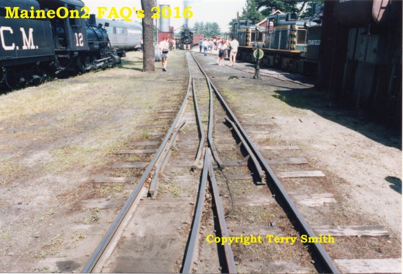
Note switch ties were 6×6 with variable length to suit. See Switches, Terry Smith.
Spacing
Precision Scale Flex track details: Code 70
Ties Actual : 1.279″ L x .153″ W x .103″ T on .406″ Centres
Scale : 5′ 4″ L x 7.3″ W x 4.9″ T on 19½” Centres
information provided by Terry Smith
- Tie Spacing From Bill Kerr “MY PERSONAL” conclusion was that anything from 18″ to 24″ was common.
I choose to model: 21″ tie spacing for mainline and my yards 18″ on tighter curves and around switches 24″ on sidings and roundhouse/engine house tracks I felt this best approximated what I was observing in photographs. I recall that pictures of the North end of Strong, had tie spacing that looked even closer then 18″, the reasoning I assumed was because the derailments that occurred in that area over the years. Robert Schlechter also pointed out that tie spacing probably decreased as heavier engines were acquired, and rail weights were increased on the Farmington – Strong – Phillips portion of the line.
- There are construction specs that work out to 18″ centers. However, if you look at Jones, vol. 2, p 108, the picture clearly shows 18″ centers under the locomotive, but 24″ centers under the coach. I’ll take a picture over a specification any day. It would be a good bet that the track crew laid marginal ties at 18″ centers, but more robust ones at wider spacing. source MaineTwoFooters Bob Troup Director, SR&RL RR
- The B&SR specified 2640 ties per mile for Quantity Surveying purposes. This works out as 24″ centres tie to tie if taken literally. However, there is also a comment that ties were placed on closer spacing where needed, such as on (serious) curves and perhaps on softer ground. It does not take many tangent ties laid at 25 or 26 inch centres to allow of curves to be laid at maybe 18 inch centres. It should also be realised that what was a quantity surveying aim maybe interpreted differently some 50 years afterward in more financially straitened circumstances, and that someone will find a picture of something different. Information provided by Terry Smith.
Creosoted?
- There is no indication that Maine two foot railroads ever used creosoted ties.
Tie Plates
- Tie plates were used, sometimes. They were three hole affairs, one hole on the inside, two on the outside. They were rectangular and made to fit a particular size rail. So, where were they used? I found some in the 1980s on the P&R Sluice Hill grade. But there were many places even on the mainline rails in Farmington, Strong, and Phillips where pictures show they were clearly missing. Were they only bought for 35 lb rail? Not used in yards and sidings? Beats me what the rules were. Source MaineTwoFooters Bob Troup Director, SR&RL RR.
- Gary Kohler has photographs for sale if you are interested.
Fish Plates
- Toby Ljung provided this modeling information from his research into fish plates. Found 4 potential sources: Roy C Link (UK), Details West (US), Monongahela Innoventions (US), Grandt line (US). I have Roy C Link’s and Details West’s fish plates at home and I’ve seen photos of the Grant line product. My verdict is simple; Use Roy C link! He produces the best fish plates I’ve seen (plastic). The only disadvantage is that they need to be slightly modified when using code 70, for code 82-100 they fit as they are. Some detail photos will follow soon on my homepage under “Layout”. Toby Ljung
“PK11 Fishplate mouldings, 48 inside (four bolt heads), 48 outside (four square nuts with shanks) – to suit Peco IL115 (code 82) rail or similar. Cosmetic only”
Now available from http://www.kbscale.com/track-parts.html £3.00 (August 2013).
Details West’s fish plate JB 922 (white metal) can be seen on these pages:
http://www.detailswest.com/switch_frog_detail_page.htm
http://www.detailswest.com/trackside.htm
August 2013: FAQ Authors note: no current link to Monongahela Innoventions can be found.
The fish plates from Grandt line can be seen on this page:
http://grandtline.com/products/images/9000’s/9003.jpg
Ballast
- It depends on the road. The Monson had plenty of slate chips. The WW&F favored not much better than dirt- with the usual wrecks as a result. So you need to be specific about railroad and era and main line, branch line, siding, Peter Tuttle HOn30 group 2004-03-17
- Yep, as Peter said, it depends. For the B&SR you need a gravel with a pinkish tan granite content and the best thing I’ve found is Saco River sand bar sand. For the WW&F and SR&RL you need a lighter tan to almost white gravel. It should not be coarse or evenly sized since they used local gravel and not sorted ballast. Even on one road the shades varied.
I use sand from the Great Northern Sand and Ballast Company. I use the TPL 40/80 mixed with SBT4080 for SR&RL. If I were doing the B&SR and couldn’t get any more Saco River sand I’d use SBR80MS. Jim models in HOn30, materials listed for reference colours
At station stops where ash would fall and be cleaned out I throw on sifted ashes I dug up in Lewiston yard in 1981. —Jim red_gate_rover HOn30 Group 2004-03-17
- You could drive up to Maine and go to Barjum branch and dig out 10 lbs of real SR&RL ballast, if you wanted to, I did years ago, its a grey/whitish. the grade is now a one lane gravel road…. chris rehm HOn30 Group 2004-03-17


You must be logged in to post a comment.