
We will start this topic with an interesting and possibly controversial quote from Dan Mitchell about model railroad locomotive “pulling power” and rolling stock friction, originally published on an Australian site which is apparently no longer available.
Actually, physics does *NOT* dictate any such thing. Both real and prototype railway locos have roughly the SAME potential pulling power. Pulling power (“Tractive effort”) is the loco’s weight on drivers times the coefficient of friction (roughly the “factor of adhesion”). This is true for both prototype and model. All else being equal, the DENSITY of a model is the same as its prototype. Thus it inherently has ‘scale weight’, and scale tractive effort.
The differences arise in that our models do NOT have “all else being equal” … they are not made of thin hollow shells of steel, but rather blocks of solid diecast metal (frames, weights, power trucks), relatively HUGE and nearly solid motors, and some thin plastic parts.
Overall, they are usually far closer to ‘solid’ than a prototype loco. Thus, they are actually MORE dense than scale, and hence often heavier than scale … this SHOULD give them MORE than scale tractive effort. That is compensated for by the ‘coefficient of friction’ issue. Real railroads are almost always ‘steel wheel on steel rail. .. this gives a friction coefficient of about 25%. Model wheels are usually brass or nickel silver wheels on brass or nickel silver track. This gives more like 18%-20% friction, so the model gets less ‘traction’ for a given weight, often remarkably close to ‘scale’. This does **NOT** take into account any ‘traction tires’ that greatly increase the friction and increase tractive effort WAY beyond scale values.
Even that is compensated for to varying degrees by the fact that our model cars have a LOT more rolling friction than real train cars. THAT (together with our often excessively steep grades) is why we often can’t pull nearly a scale length train.
And that’s why I stated in a recent earlier post that “If you want to pull long trains, you should spend a **LOT** more time reducing your rolling stock’s friction (metal wheels, better trucks, etc.) than worrying about increasing your locomotive’s pulling power.”
Now we will present the Maine On2 specific information collected by Terry Smith, note that clicking on each table produces a larger view. Use your browser back arrow to return to the topic.
When Terry first published this information, in his introduction he wrote “One conclusion, just to state the obvious, is that friction and drawbar pull experiments/measurements suffer from a lack of repeatability. I already knew that would be the case having spent 24 years as a practising engineer in the friction reducing field, but it came back to bite me with today’s tests!”
Notwithstanding Dan Mitchell’s comments above, then we may plead that On2 is a special case, where the iconic locomotives, such as the small Forney’s, have very much smaller boilers compared to typical engines used on most model railroads and the limited commercial availability of alternative designs of trucks means that our options for reducing truck friction are also limited. Enjoy reading this data and then make your own decisions, not forgetting to look inside the boilers to see what weights the manufacturer has installed.
Measured draw bar pulls and other information for Forney style On2 Brass Locomotives.
The forces presented in these tables were measured using 0-1 N forcemeter (essentially a 100 gram spring balance). In the static loco cases, the forcemeter was attached to the rear coupler by a loop of cotton thread and the free end of the forcemeter was pulled, and the steady reading taken.
In the case of the drawbar pull measurements, the forcemeter was attached to the rear coupler by a loop of cotton thread and the loco was driven away slowly until the drivers slipped.
The On3 Shay values were determined with a 0-10 N forcemeter (essentially a 1000 gram spring balance).

On2 Track used was Precision Scale with code 70 nickel silver rail.
On3 Track used was Precision Scale with code 83 nickel silver rail.
The modified Custom Brass SR&RL #6 has additional weight fitted inside the boiler.
The two On3 locomotives are included for the sake of comparison as they demonstrate what can be achieved by having all the locomotive weight available on the drivers (by being equalised) for the two commonest driver tyre materials.
Measured draw bar pulls and other information for some SR&RL 2-6-2 On2 Brass Locomotives

On2 Track used was Precision Scale with code 70 nickel silver rail.
Measured coefficients of friction for some SR&RL 2-6-2 On2 Brass Locomotive tenders (only)

Coefficients of friction measured by inclined slope method.
Static refers to the maximum slope which can be resisted before motion takes place.
Dynamic refers to the slope down which the item continues to move at constant speed once started.
Notes;
Custom Brass SR&RL #16 Locomotive and Tender
This locomotive and tender are essentially as built by Custom Brass. The poor drawbar pull figures with slipping drivers are partly explained by a slipping shaft coupling.
Custom Brass SR&RL #18 Locomotive and Tender
This locomotive has been extensively modified and features in the Custom Brass SR&RL #18 post on this site. Click here to view on another page.
Moving the drive to the rear axle has allowed more of the boiler space to be used for lead weights, which accounts for the extra weight of this locomotive and it’s higher drawbar pull.
The tender has a special version of the PFM Sound system installed (with an off switch) and has also been extensively modified. Work done includes rebuilding the trucks to be equalised and installing extra power pickups for both sides of the track. The wipers contact the backs of the wheels and are most probably the reason why this tender appears to have poor frictional characteristics.
Custom Brass SR&RL #24 Locomotive and Tender
This locomotive and tender have had PFM Sound installed, and most probably some attention to the drive train, otherwise it appears to be stock Custom Brass.
General
The information for these locomotives is presented in this form because whilst the locomotive is essentially the power source, it is not normally operated without the tender, which functions like a very heavy and badly running freight car, ie reduces the drawbar pull available to pull trains.
Measured coefficients of friction for On2 and On30 trucks and rolling stock

On2 unless otherwise stated.
Freight cars have Grandt Line trucks with NWSL wheelsets unless otherwise stated.
Coefficients of friction measured by inclined slope method.
Static refers to the maximum slope which can be resisted before motion takes place.
Dynamic refers to the slope down which the item continues to move at constant speed once started.
Note that some trucks did not show a higher coefficient of static friction on these tests.
Nickel silver rail code 70 used.
Friction definitions, data and online calculator websites
The following external links are shown in lieu of any explanations written by the blog editors, as they are probably better than we could write.
A couple of sites showing the forces involved and explanations of friction and lifting bodies up inclined planes, with online calculators;-
http://www.engineeringtoolbox.com/friction-coefficients-d_778.html
http://www.engineeringtoolbox.com/inclined-planes-forces-d_1305.html
A set of sites giving basic data and simple explanations about friction;-
http://www.easycalculation.com/physics/classical-physics/friction-table.php
http://www.easycalculation.com/physics/classical-physics/learn-static-friction.php
http://www.easycalculation.com/physics/classical-physics/static-friction.php
http://www.easycalculation.com/physics/classical-physics/learn-kinetic-friction.php
http://www.easycalculation.com/physics/classical-physics/kinetic-friction.php
Advanced considerations; position of centre of gravity and additional weights
In this section we present some advanced considerations where Terry has measured the effect of moving the position of the centre of gravity with respect to the driving wheels at constant all up weight for several On2 loco’s, and in some cases adds additional weight to simulate the effects of either increasing the size of the OEM boiler weight or changing it to tungsten.
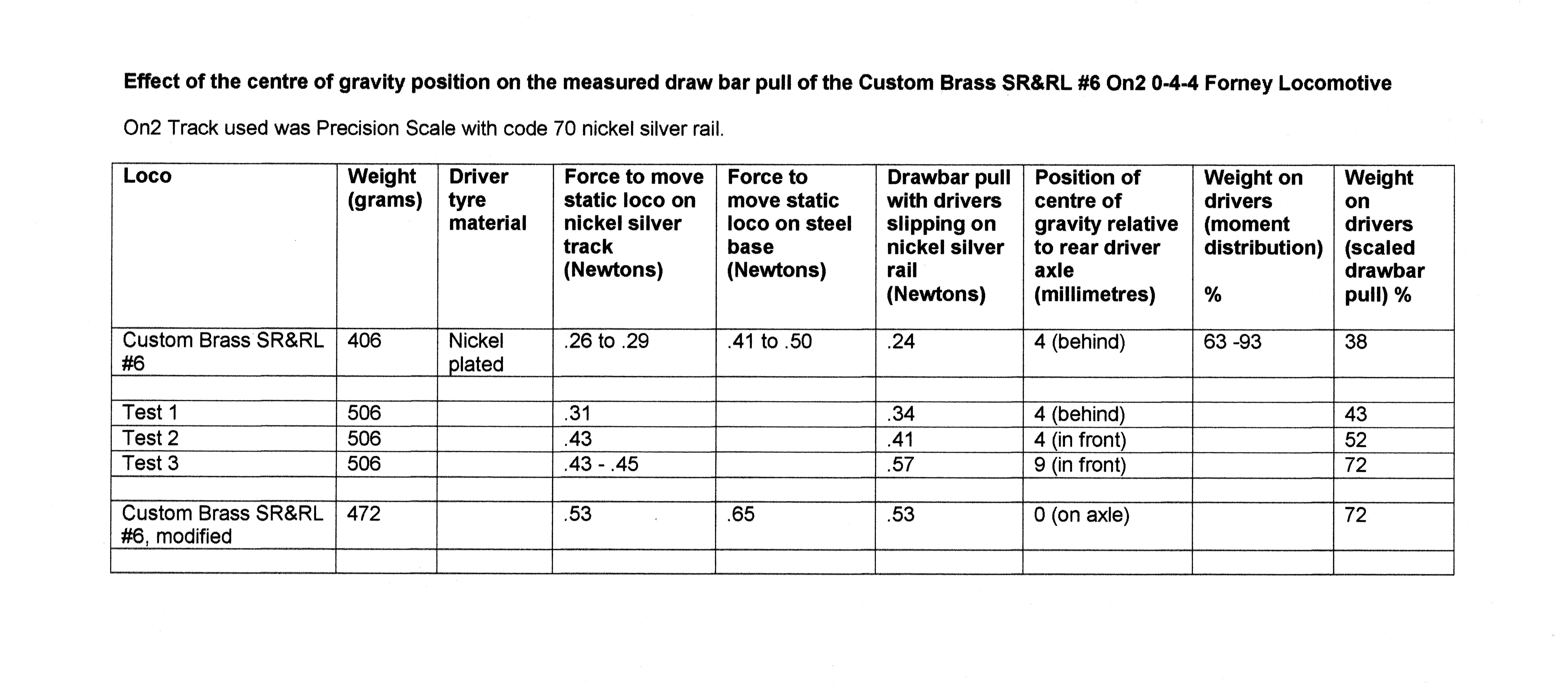
In this series, the basic loco has been fitted with a Faulhaber 1624 coreless motor, and it originally weighed 406 grams. Terry calculated that the maximum lead weight size that would fit within the boiler would take this weight up to 506 grams. So far, Terry has managed to get the locomotive weight up to 472 grams.
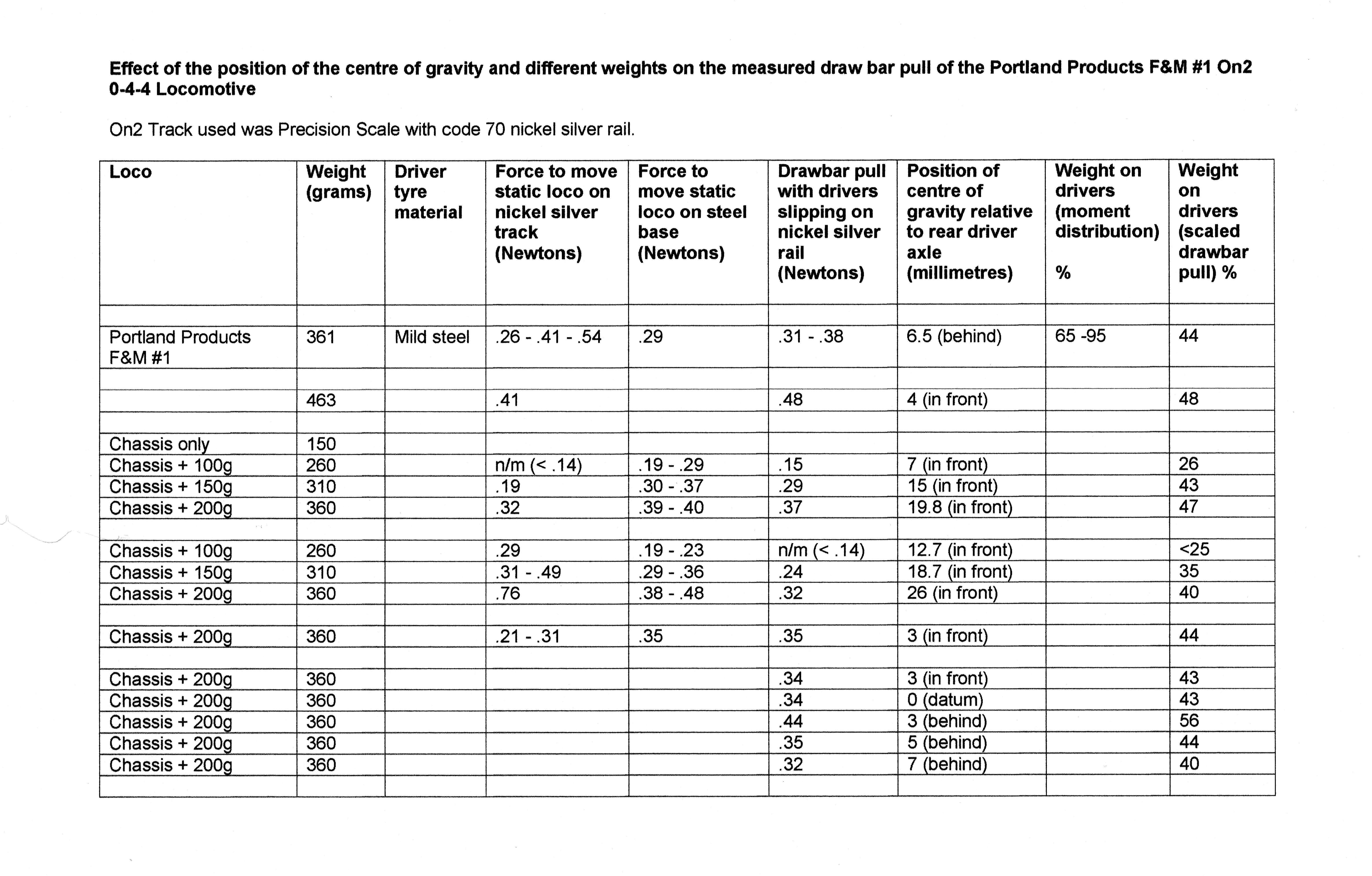
In this series of tests, Terry used the Portland Products F&M #1 chassis to carry a series of laboratory weights in different positions to investigate how the measured drawbar pull varied with total weight and centre of gravity position. The suggestion is that there is an optimum position for the centre of gravity, in this case 3mm behind the rear driver axle centreline.

In this series of tests, Terry used his modified Custom Brass SR&RL #18, without the pilot and trailing trucks to investigate how the measured drawbar pull changed with centre of gravity position and total locomotive weight.
Terry calculated that the OEM weight could be increased by 100 grams and still fit within the boiler space, and that if the lead was substituted by tungsten then the weight would increase by 210 grams.

In this series, Terry shows the locomotive in original condition, with a measly brass boiler weight of just 43 grams, and what the loco could pull if the boiler weight was maximum size in lead, taking the weight to 700 grams.
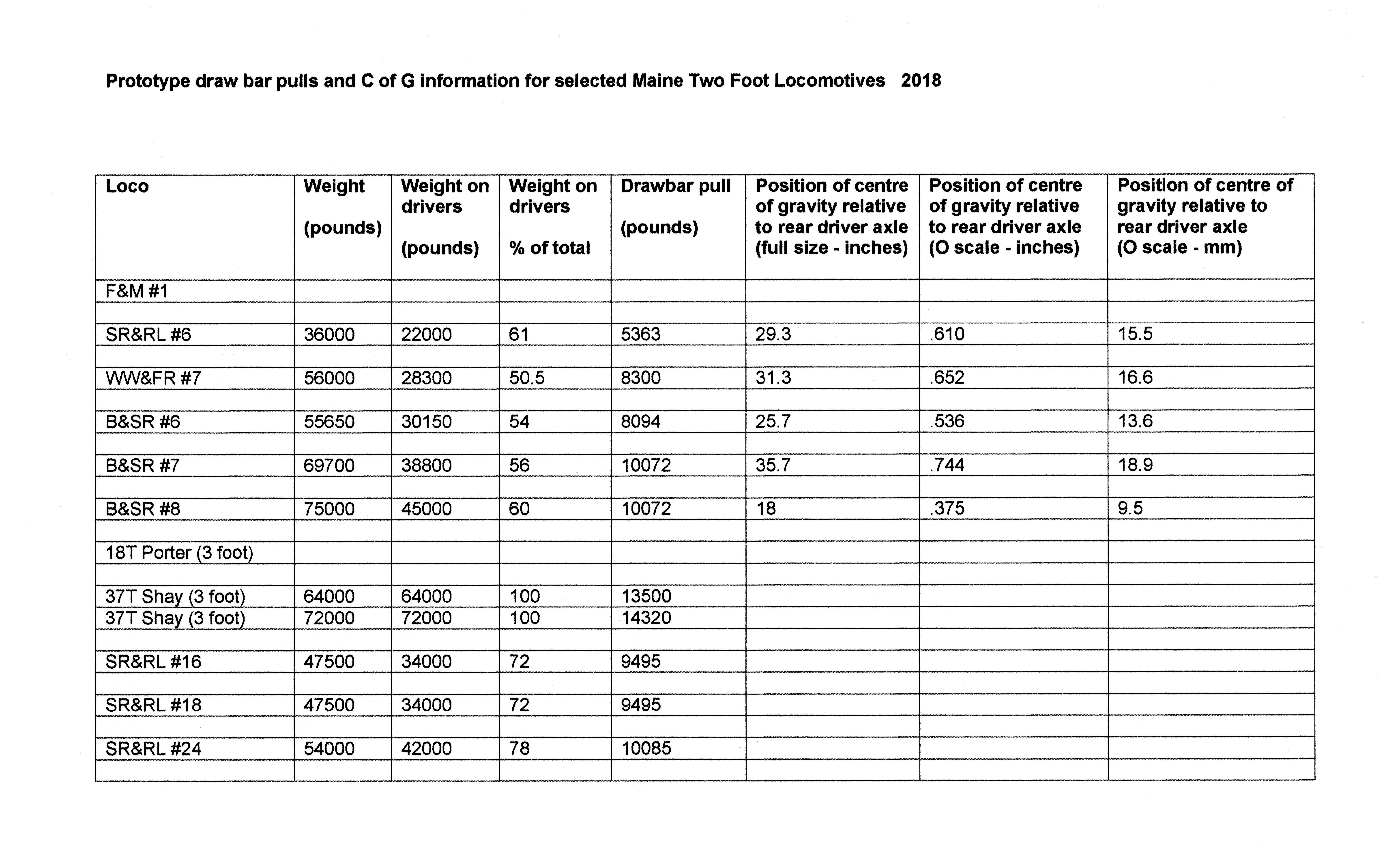
Drawbar pulls and other information for selected Maine Two Foot prototype locomotives.
The following table is presented for the sake of information only. It is not intended to suggest any practical guidelines for model locomotives.
Notes:
Entries left blank are deliberate because accurate information could not be found or determined.
The prototype Forney C of G’s have been calculated from published weight information and plans, and all are behind the rear driver axle.
The On3 3 foot Shay model used for comparison is shown in error as a 37 Ton version in the table above. The prototype engine was factory number 1896 built in 1907 for the Diamond & Caldor Railroad as their #4, listed as a 36 ton version.
The topics of drawbar pull and truck friction are related to the maximum grade capability which on these FAQ’s is a separate topic. Click here to view on another page.


You must be logged in to post a comment.