Way back in the Autumn of 2021 in the UK, the second year of Covid lockdown restrictions were easing and things were getting back to normal. A number of smaller locally organised train shows were taking place, and Bob Harper got an invite to take Franklin to the Tolworth Showtrain Exhibition. Bob enjoys exhibiting his layouts and on this occasion his layout was photographed by Andrew Burnham from the staff of the UK magazine, Continental Modeller, with a view to using them to illustrate a possible future article.
Andrew sent Bob a copy of the shots taken, with permission to publish them on blogs as long as they were attributed to “Andrew Burnham, courtesy of Continental Modeller”. For more information about Continental Modeller click here.
Bob forwarded a set of pictures and we present our selection and edits.
The flyer announcing the Tolworth Showtrain. This particular show was described as “Always a good balanced mainstream event; not too finescaley and not aimed at families either. Perhaps for ‘the average modeller’.” Click here to view the comment and more discussion about the show on a UK blog.
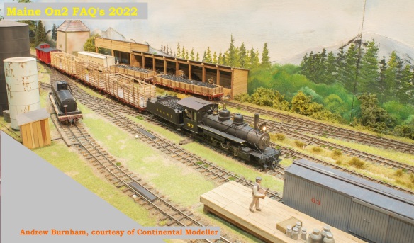
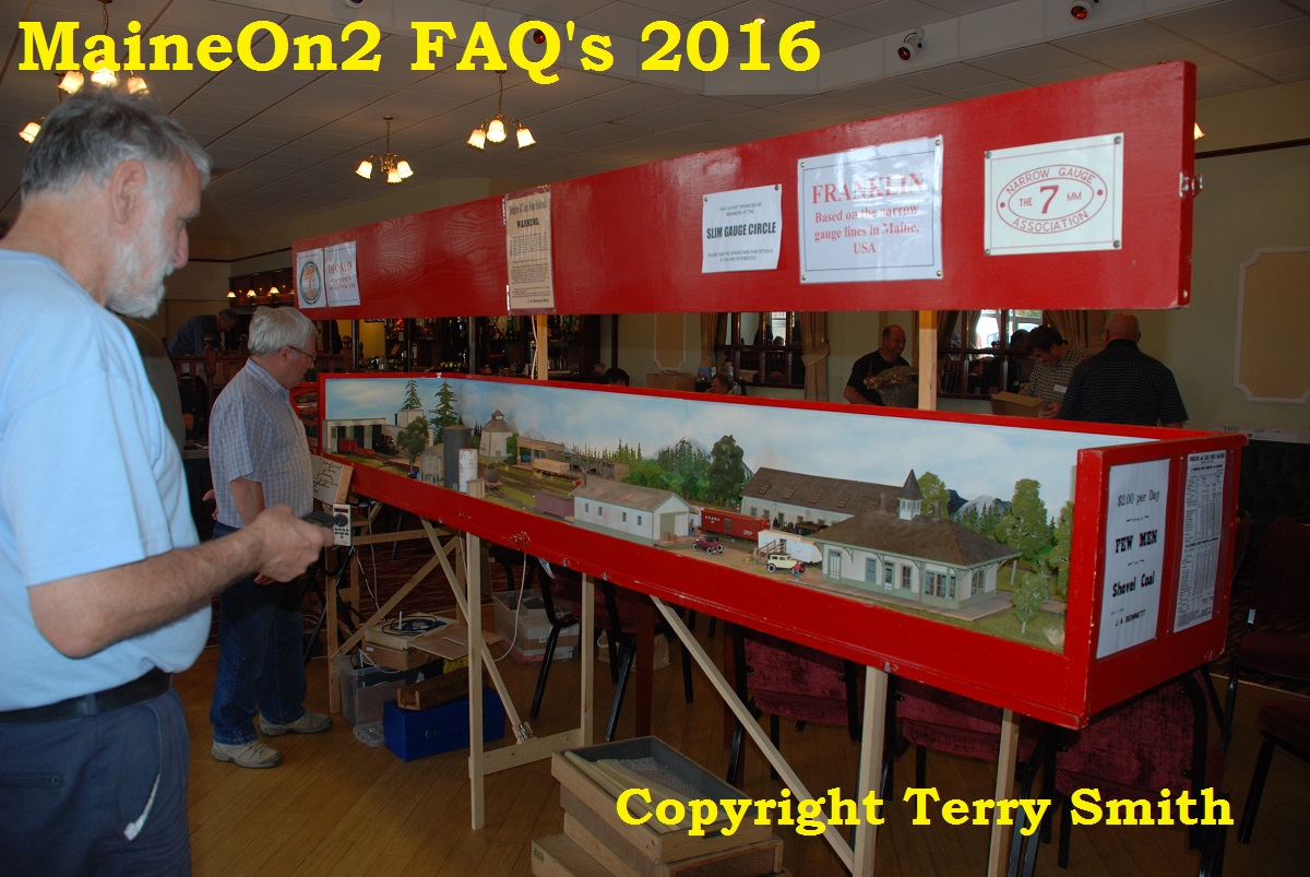
This look down view, taken from the gallery gives a good overall view of an early Sunday morning at a typical UK model railway show, as well as the whole Franklin layout with Bob Harper sitting on the stool at the front where he can operate the trains and the turntable in the fiddle yard behind him, while conversing with the paying public.
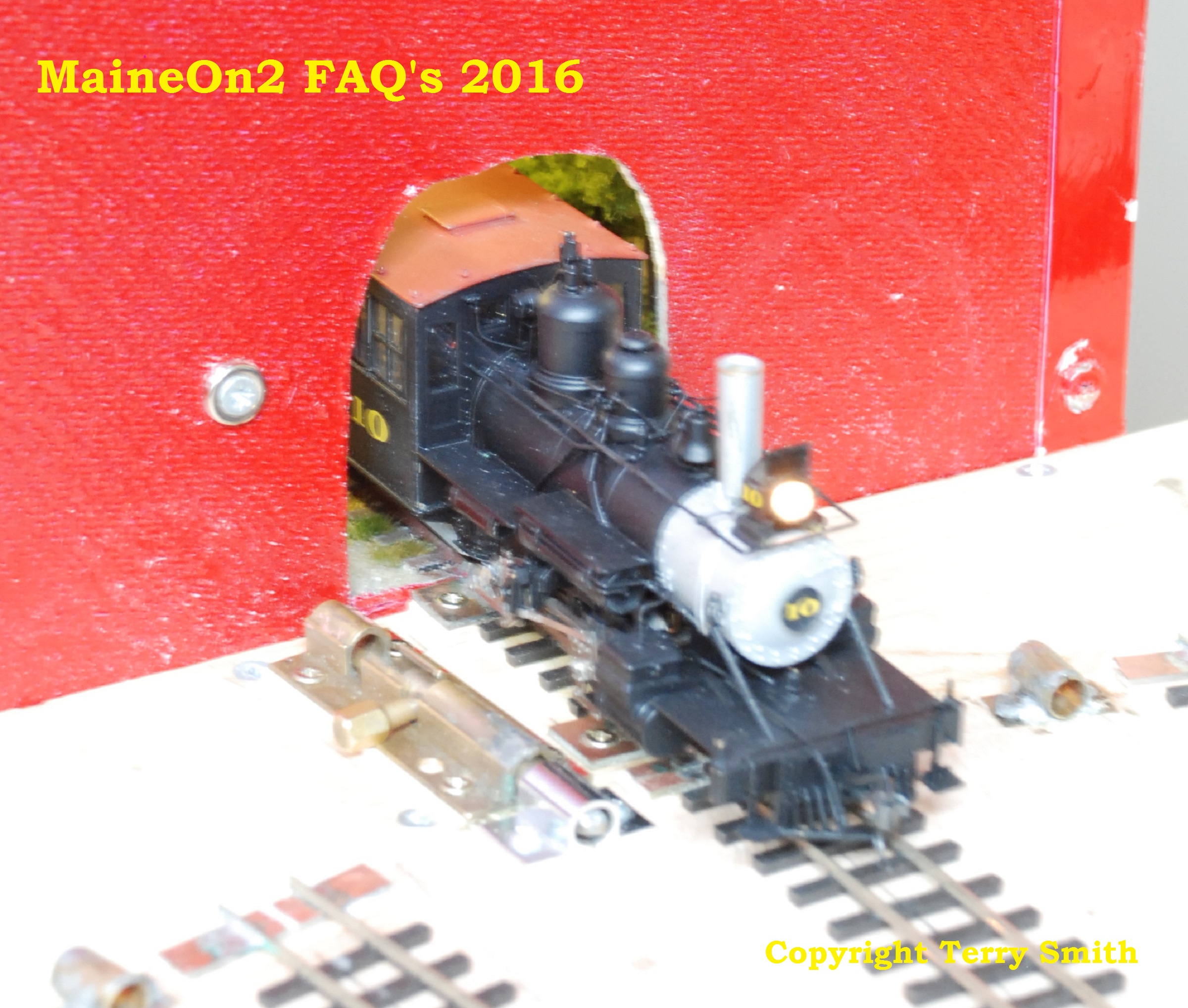
Loco #24 being turned for its return journey
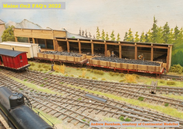
Loco #23 arriving at Franklin with a rake of empty pulpwood rack cars scratch built by Bob.
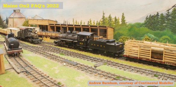
Loco #23 waits to depart with a log load carried in the pulpwood rack cars, while loco #9 arrives with a general merchandise freight train.
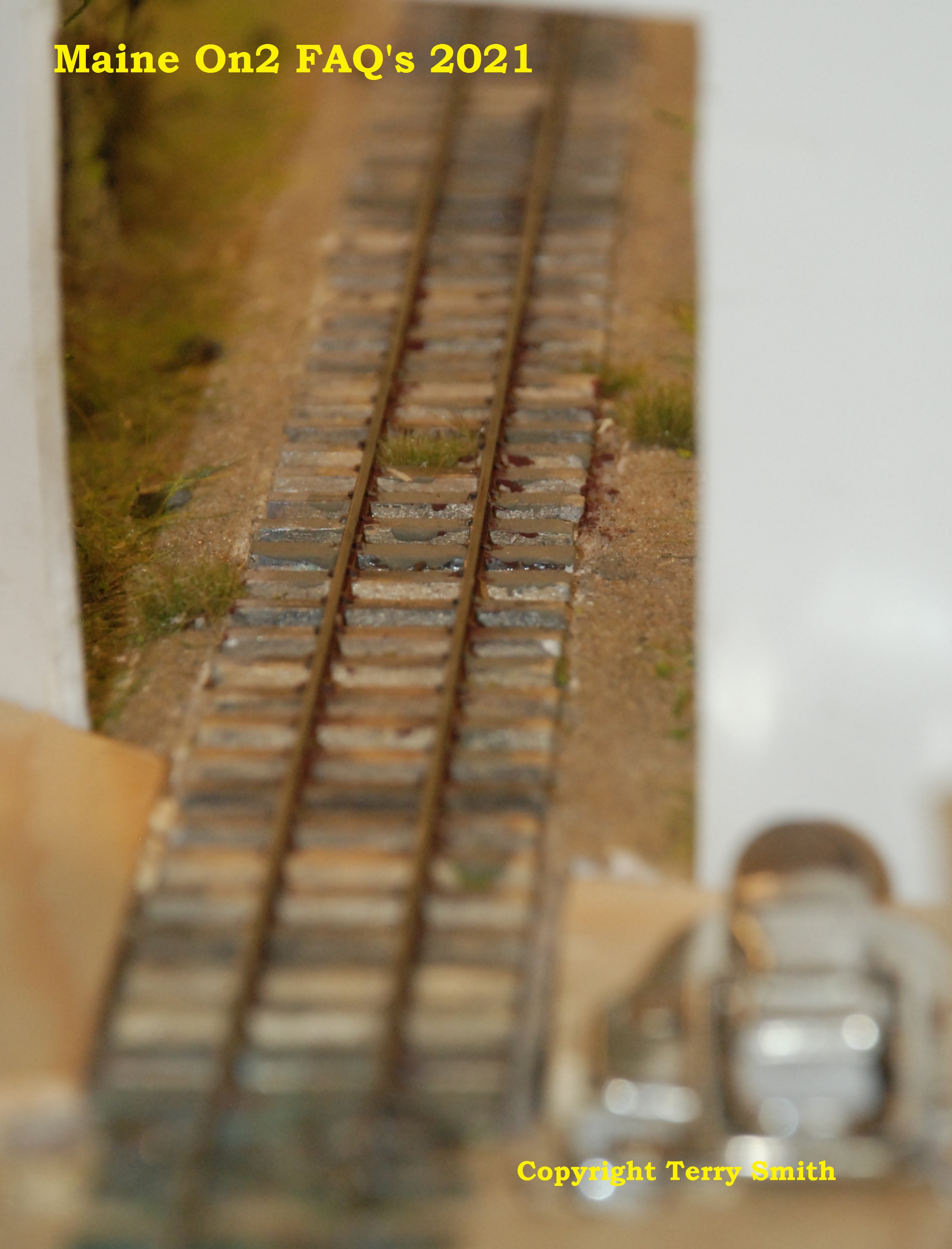
This picture shows Bob’s hand built trackwork well.
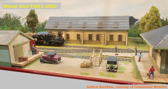
Loco #10 with its passenger consist keeps the arrival road and the run round clear for arriving trains. Note the heavily weathered Bridgton boxcar.
A Consolidated Mining & Smelting Shay (far from home) brings in a log load.
Bob’s scratchbuilt model of the Sandy River #6 combination car.
Bob’s scratchbuilt model of a Sandy River cattle car.
The end of the line, showing the whole sceniced portion of the layout.
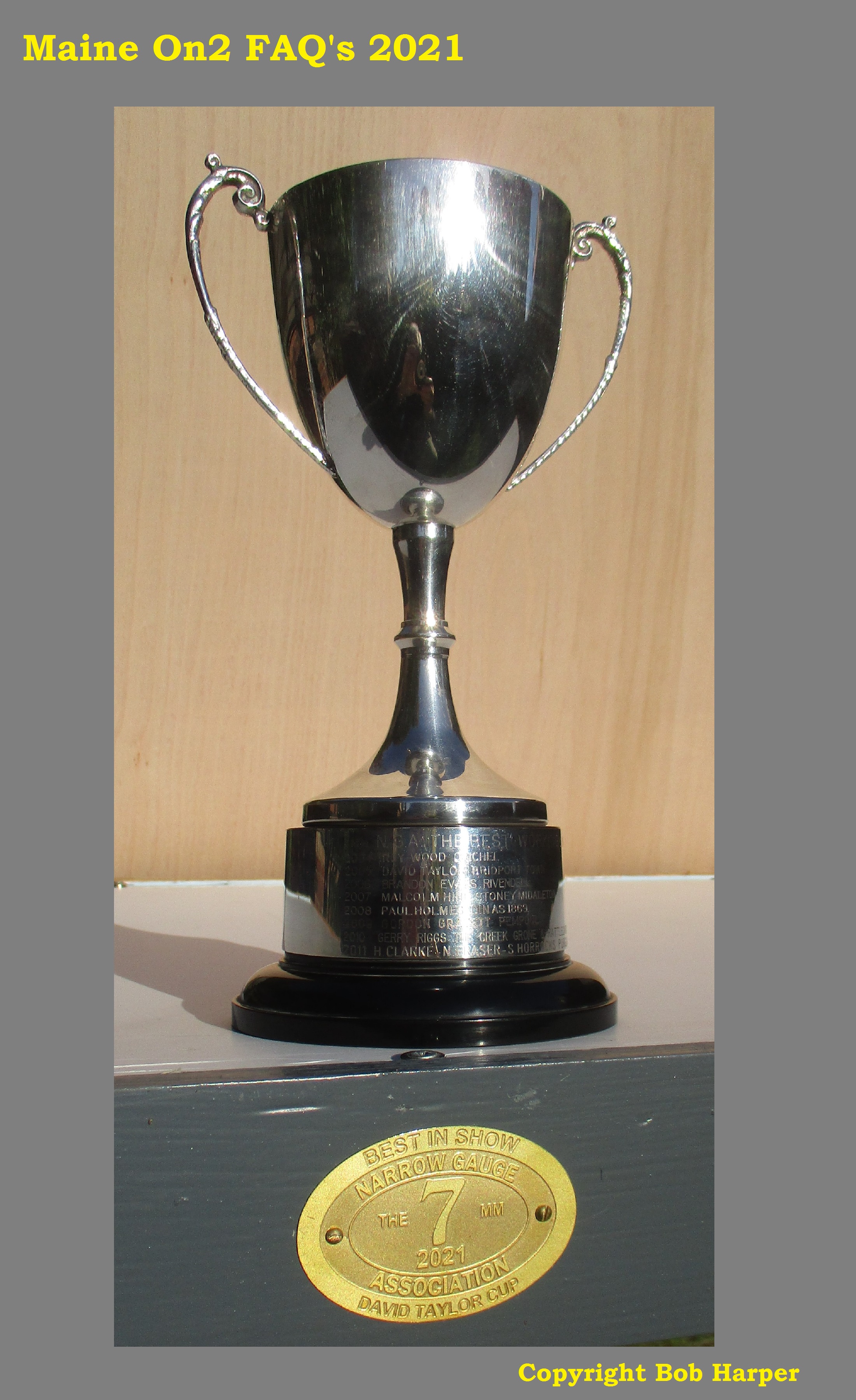
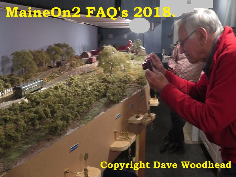
The New Sharon layout had a booking to appear at the UK 7mm NGA Exhibition on the 16th October 2021 at Burton-on-Trent. The pictures that follow show the “behind the scenes” operation to prepare the layout for its return to the UK Exhibition Circus after an eighteen month break. The exhibition visitors obviously enjoyed the layout voting it the “Best in Show”.
The award consists of a brass plaque permanently attached to the layout and the David Taylor Cup held for a year.Well done Bob!.
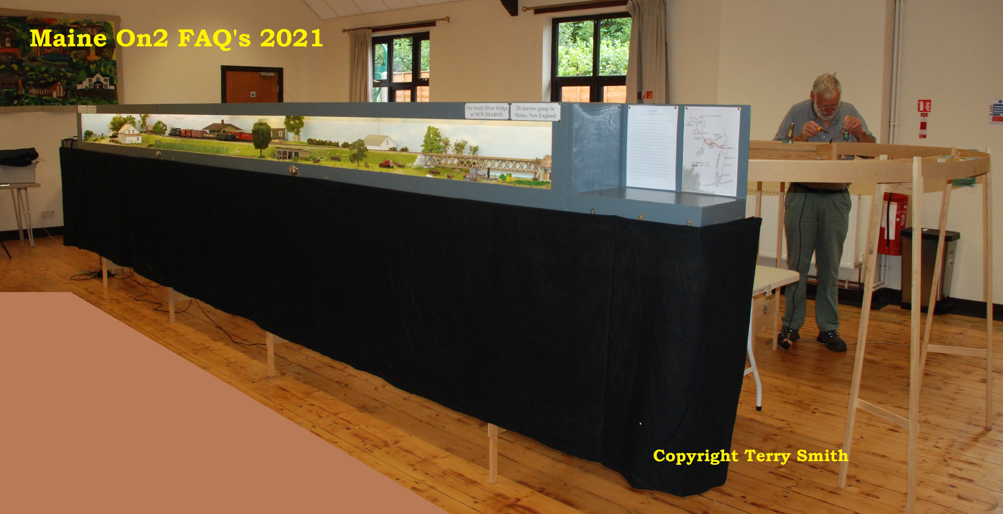
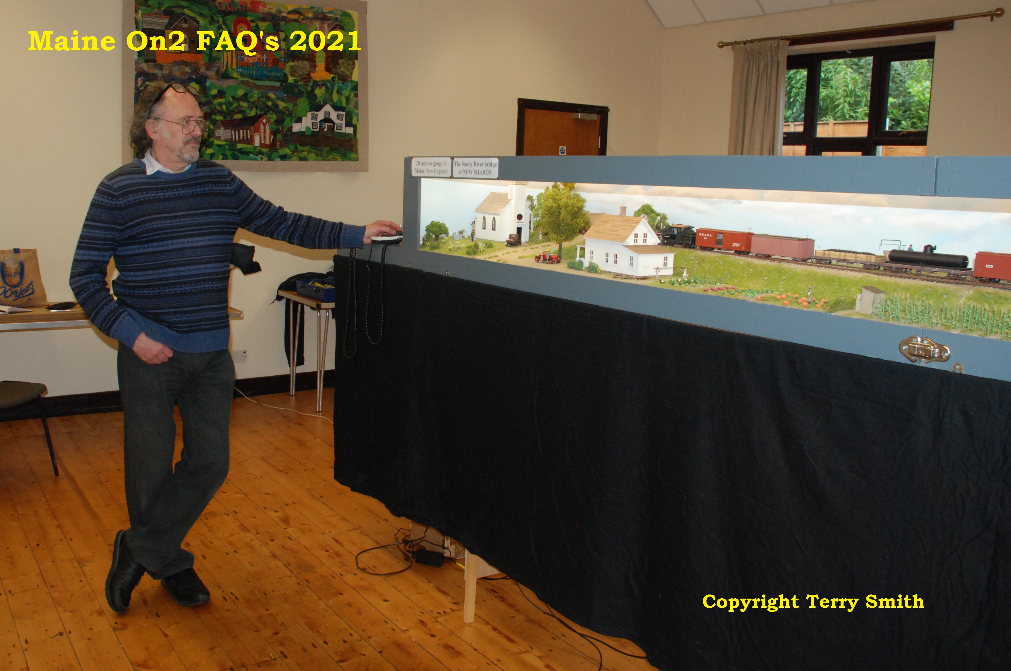
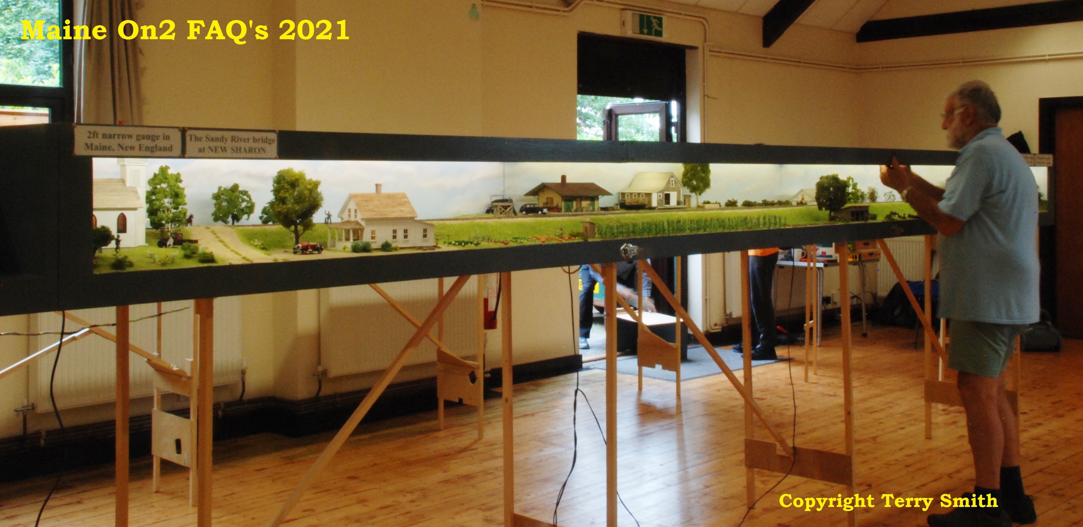
The man and his layout: Bob Harper and New Sharon in Llanbedr Village Hall
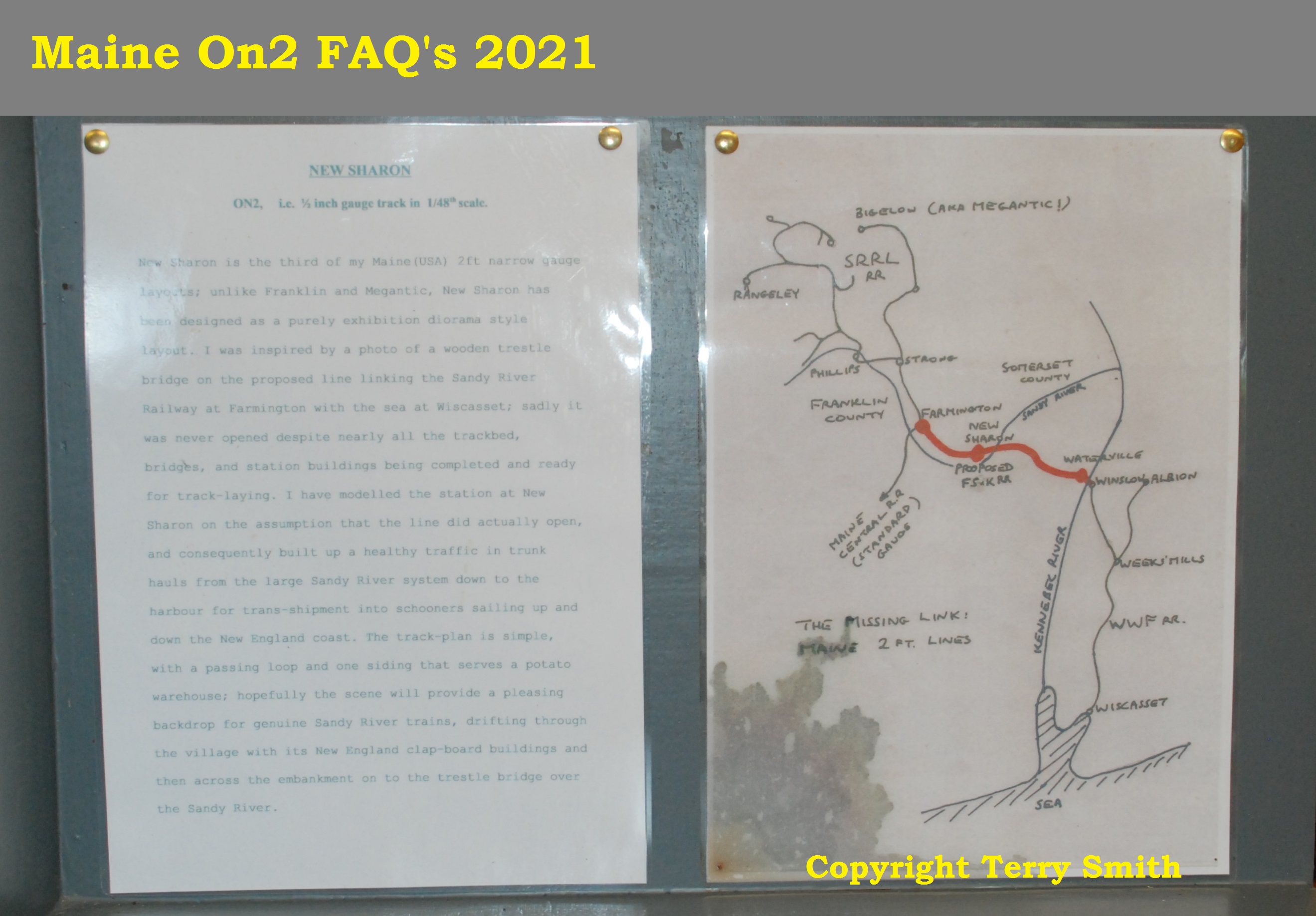
Bob wrote a brief introduction to his New Sharon Layout for Exhibition managers and the viewing public which is copied below. A copy is posted in the niche at the right hand end of the layout for the benefit of exhibition visitors.
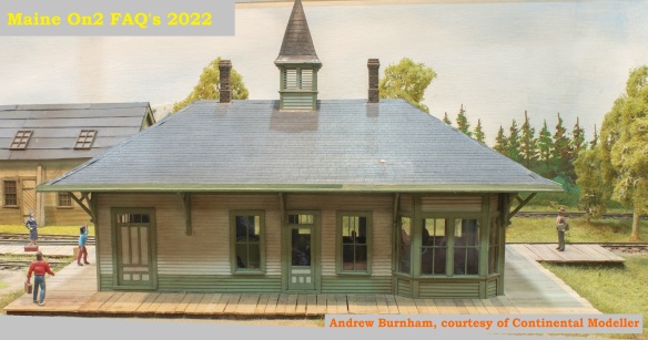
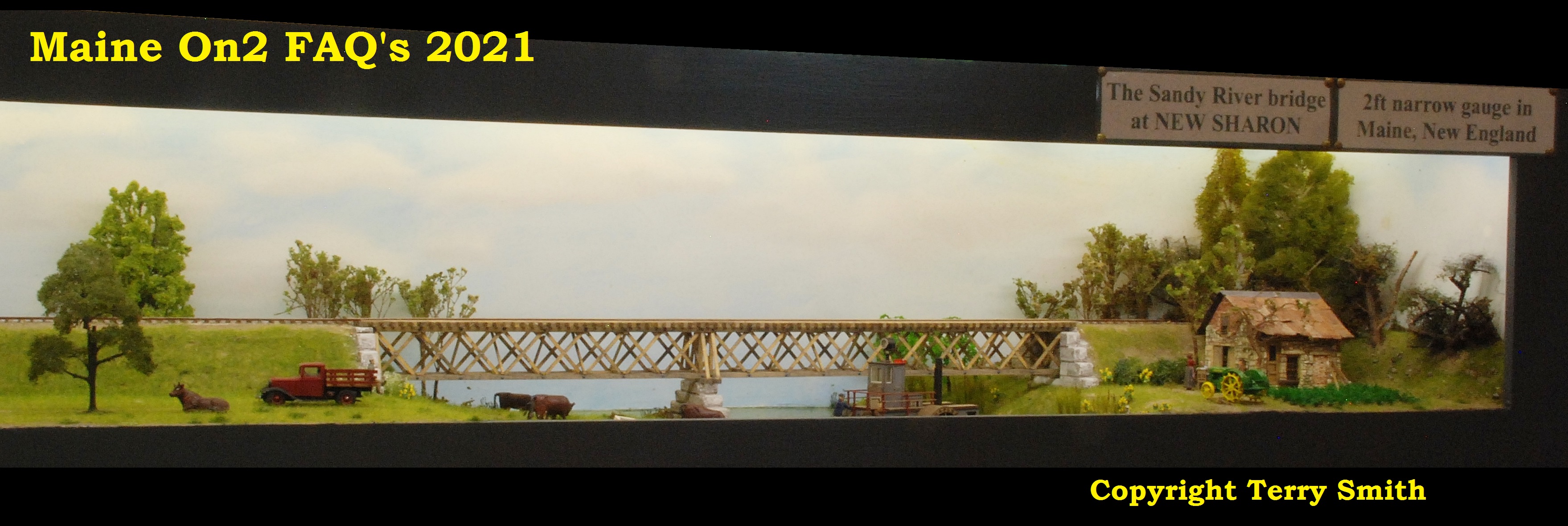
New Sharon is the third of my Maine (USA) 2ft narrow gauge layouts; unlike Franklin and Megantic, New Sharon has been designed as a purely exhibition diorama style layout. I was inspired by a photo of a wooden trestle bridge on the proposed line linking the Sandy River Railway at Farmington with the sea at Wiscasset; sadly it was never opened despite nearly all the trackbed, bridges, and station buildings being completed and ready for track-laying. I have modelled the station at New Sharon on the assumption that the line did actually open, and consequently built up a healthy traffic in trunk hauls from the large Sandy River system down to the harbour for trans-shipment into schooners sailing up and down the New England coast. The trackplan is simple, with a passing loop and one siding that serves a potato warehouse; hopefully the scene will provide a pleasing backdrop for genuine Sandy River trains, drifting through the village with its New England clap-board buildings and then across the embankment on to the trestle bridge over the Sandy River.
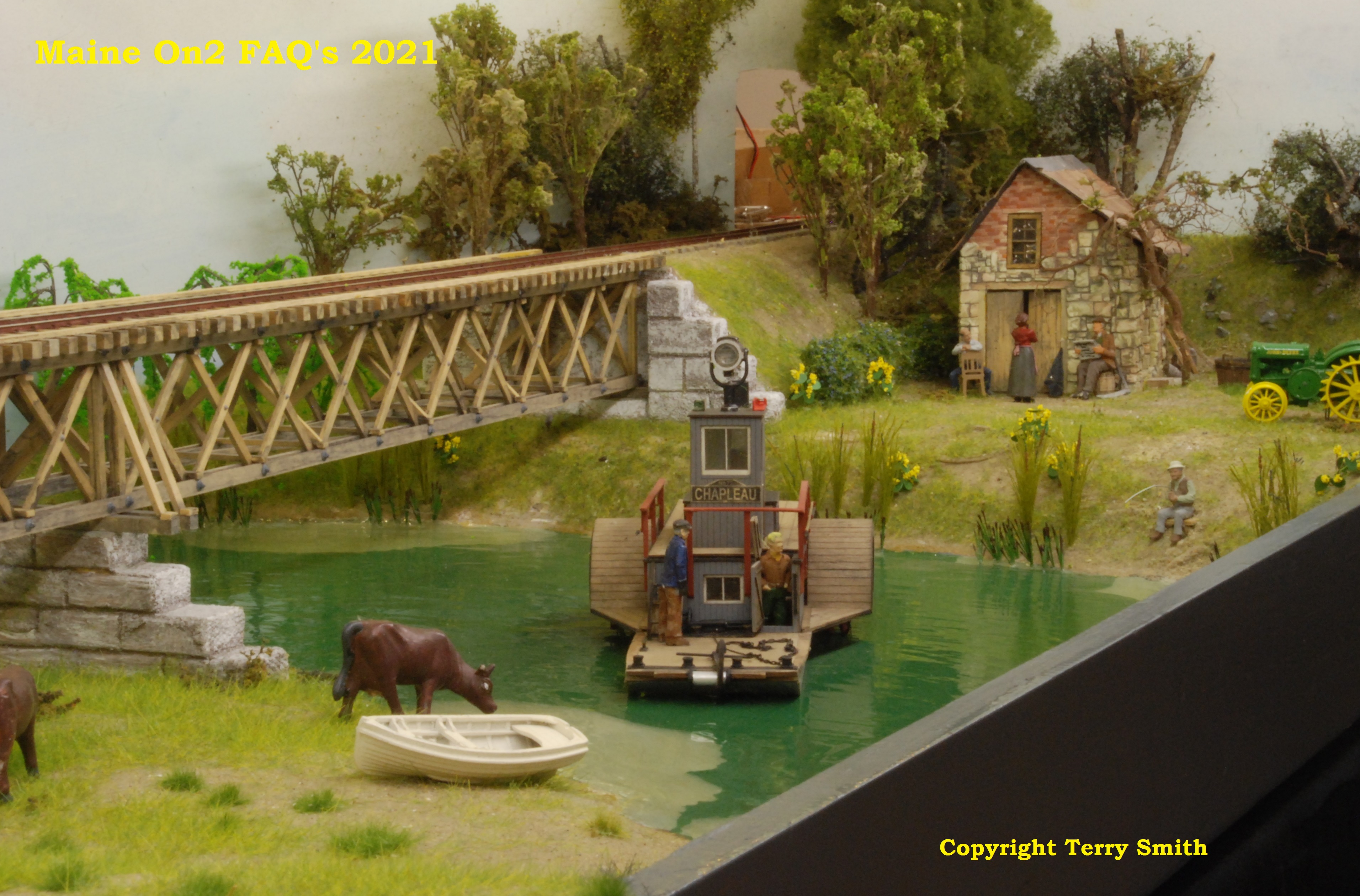
Bob’s model of the bridge that inspired him to build the whole layout.
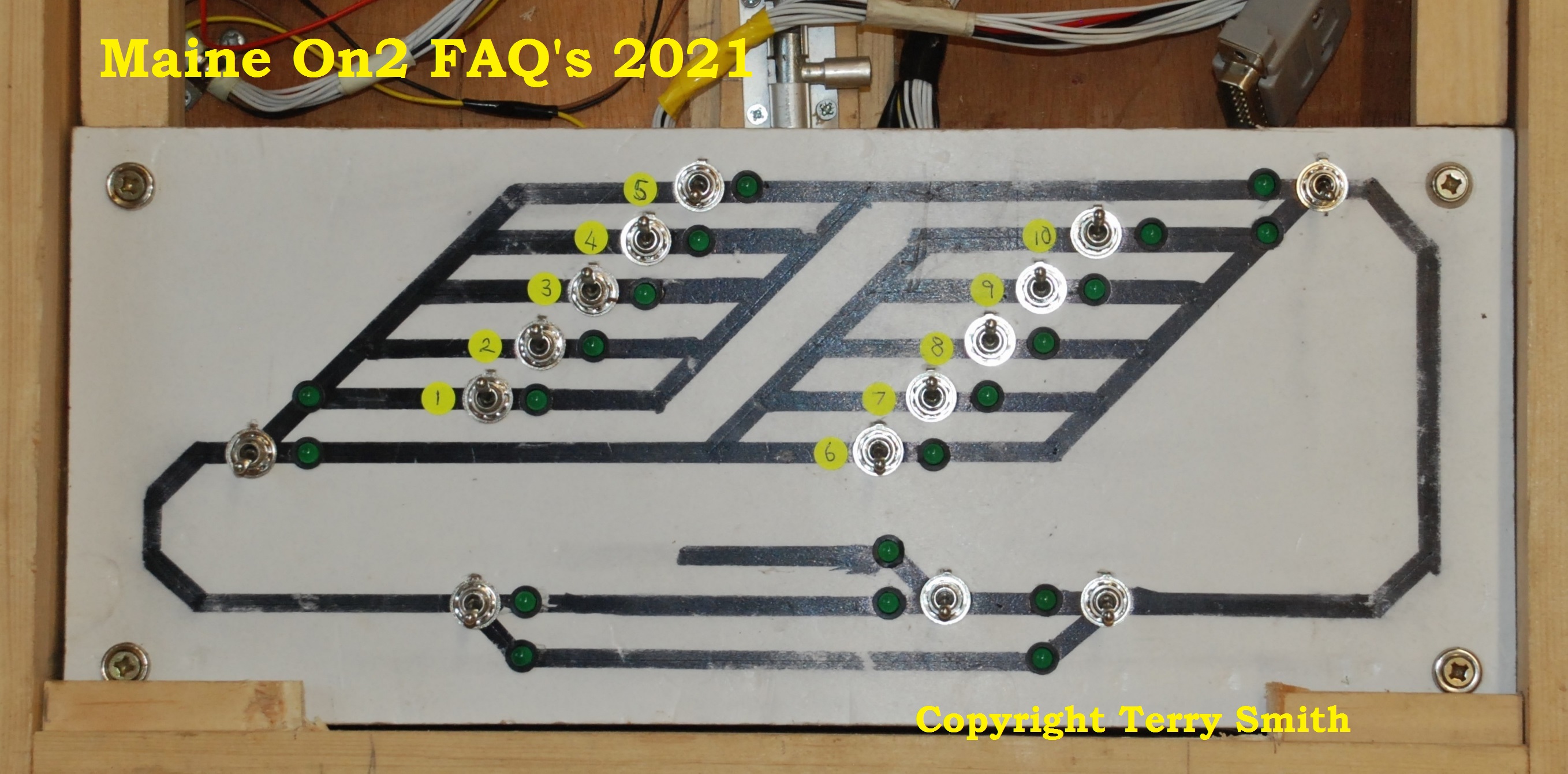
The control panel shows the track layout. The lower portion is the sceniced viewing area, and the storage yards are at the back of the layout. The end curves are around 36″ radius and are partially hidden from view by niches extending from the scenic areas.
The layout is 25 feet long by nine feet wide and stands with the track level at 52″ above floor level. The main viewing area at the front is 18 feet long, consisting of three open fronted “C” shaped modules, each six feet long by 22″ deep and 15″ high. These modules contain all the scenic features permanently fixed, with an integral backscene and top cover with integral LED strip lighting. Each module has legs which fold up into the respective module floor for transportation and storage.
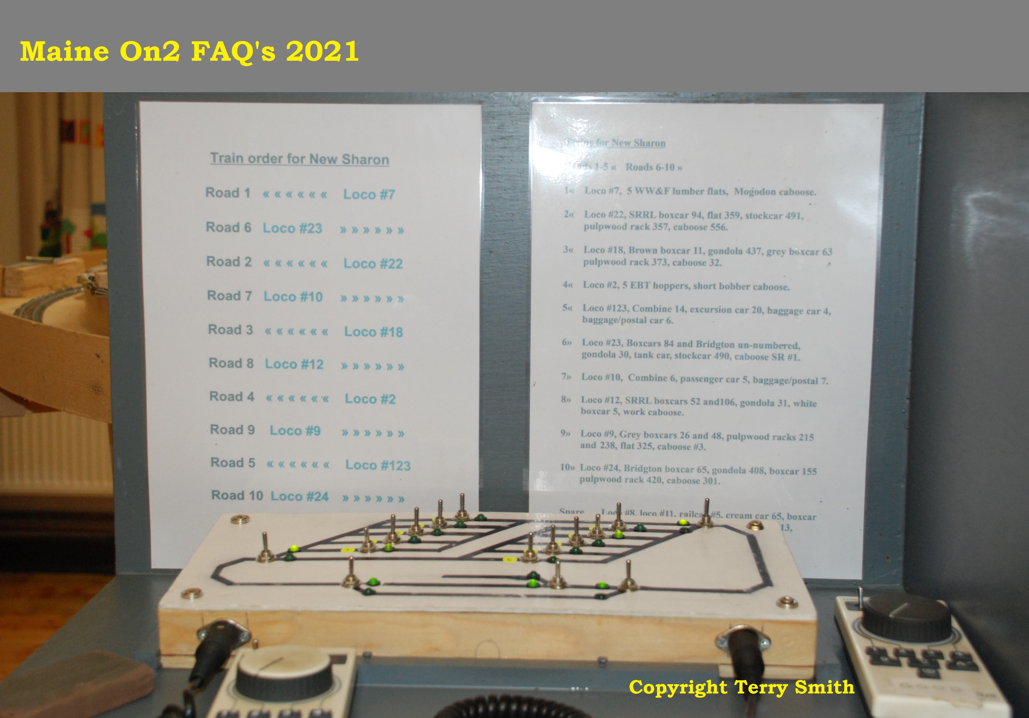
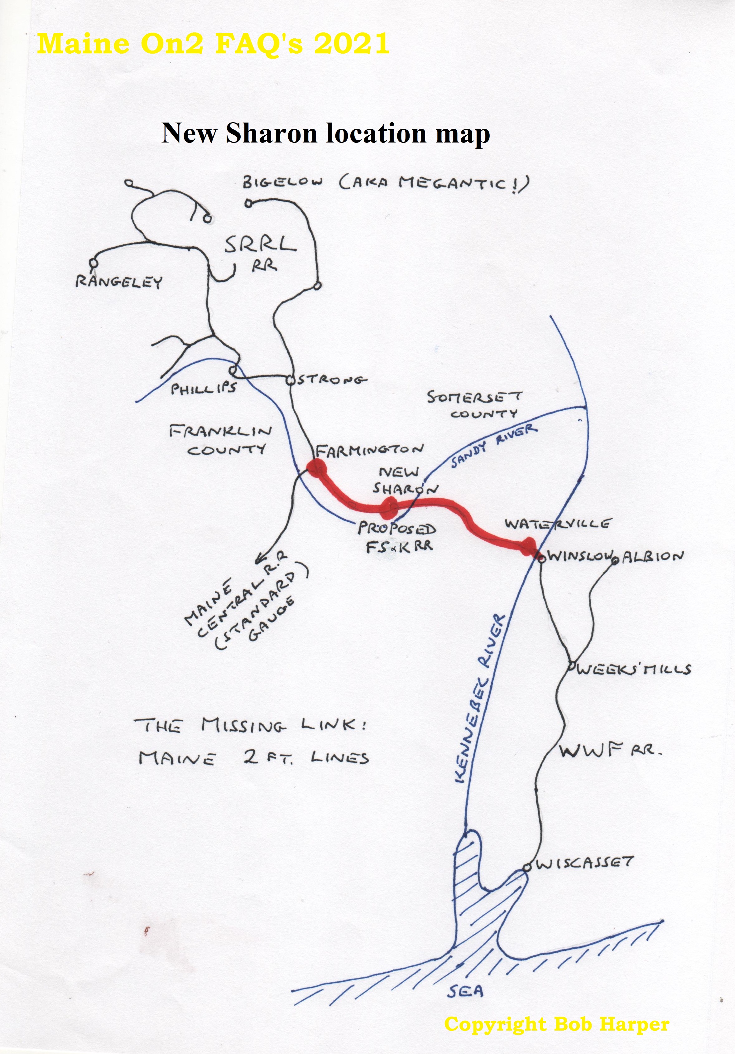
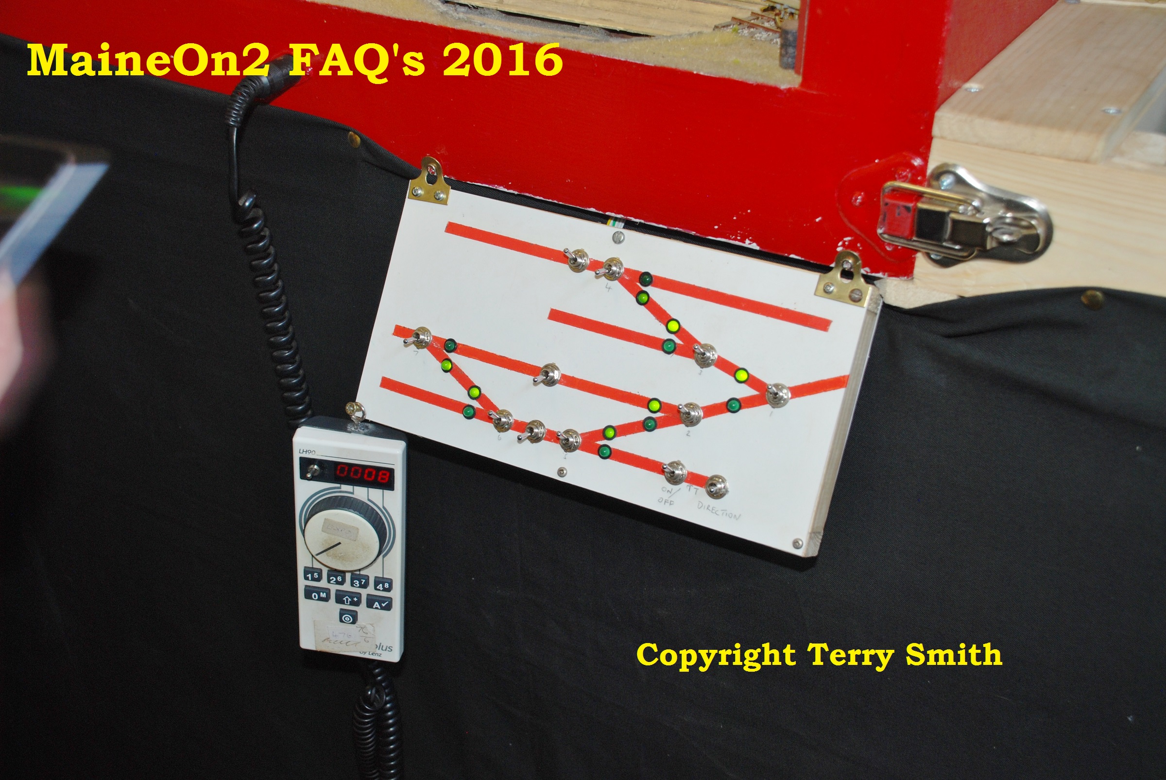
At either end of the sceniced section are niches, the left hand one is the control station fitted with the controls for all pointwork and route selection, and two DCC throttles. The train consists, their storage tracks, and running orders are displayed on the vertical backboard to this niche. The niche at the right hand end has the introduction (above) and a map of Maine showing the location of New Sharon and the line of the proposed Franklin, Somerset & Kennebec Counties Line which would have linked the SR&RL to the Wiscasset line and the sea port of Wiscasset.
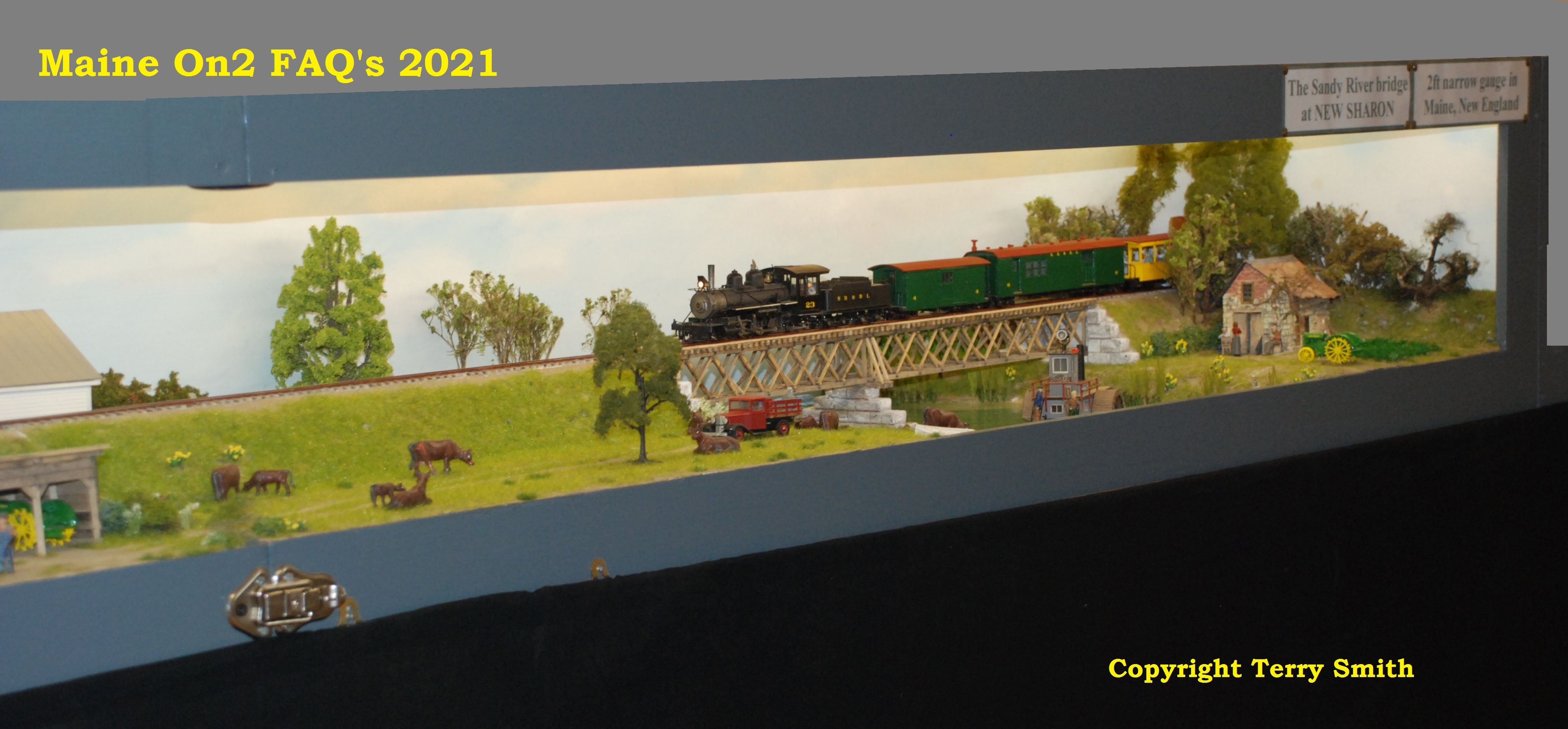
The bridge crossing the Sandy River at New Sharon is at the right hand end of the sceniced area. Notice how well the entry point through the curved backscene is hidden by the foliage.
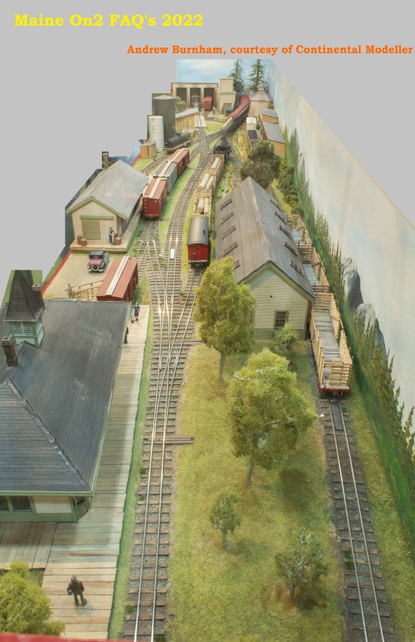
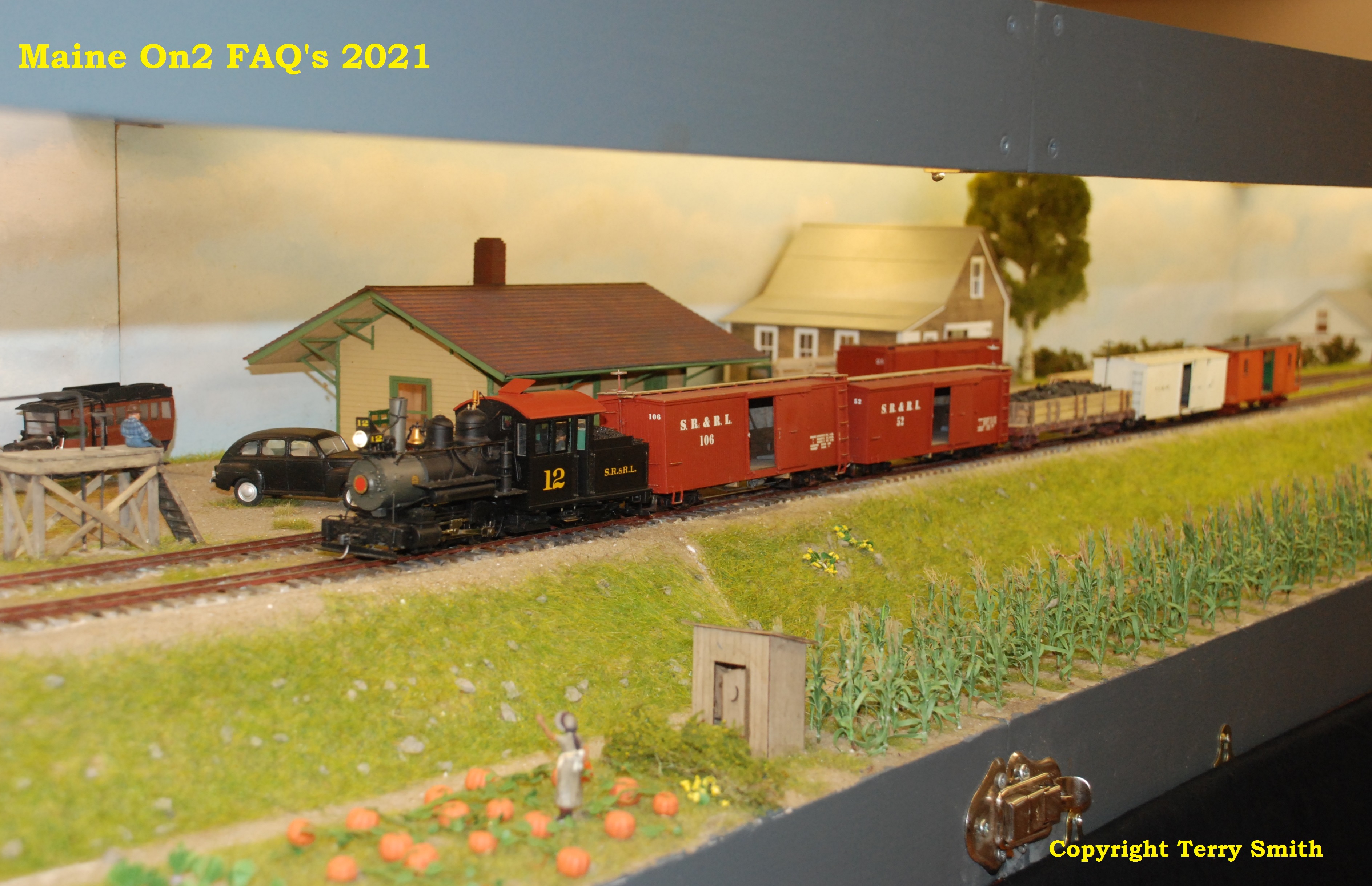
The middle section contains a typical Wiscasset style station and a warehouse. This picture shows the embankment style construction which has the benefit of allowing the Tortoise motors used for switch operation to be totally enclosed within the module structure, which have flush top and bottom surfaces for transportation and storage.
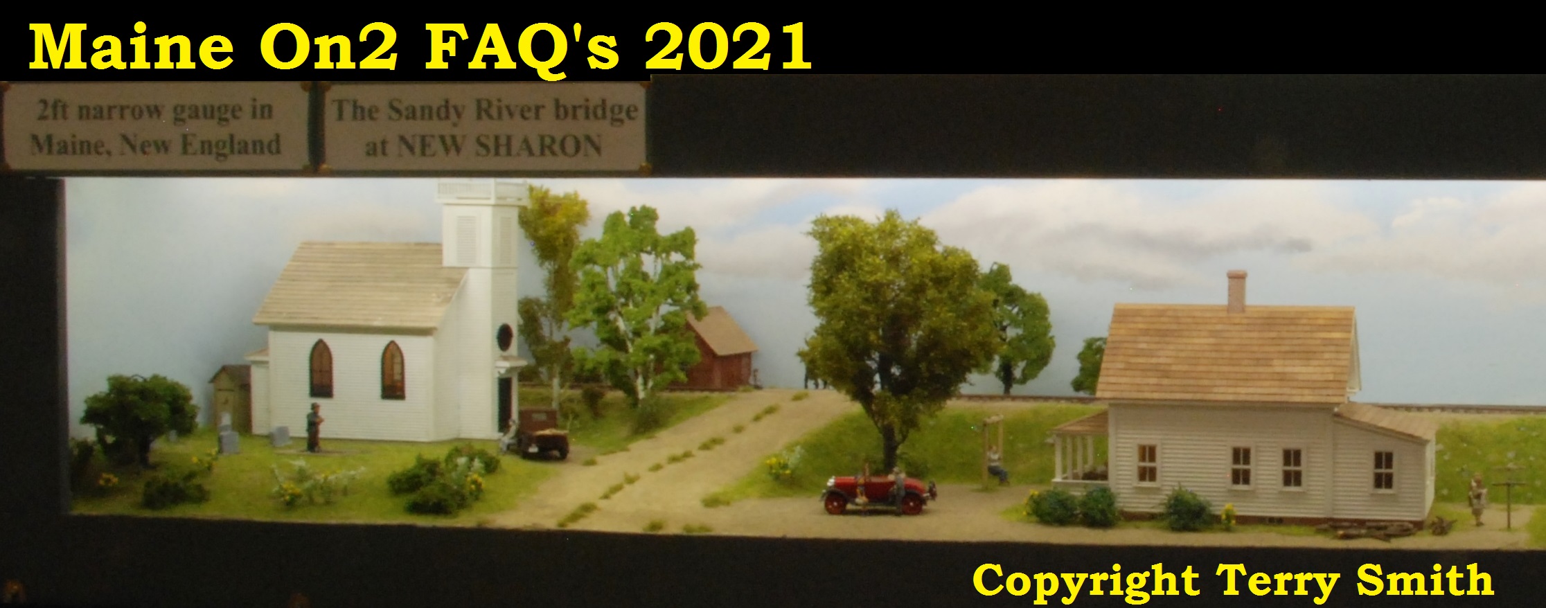
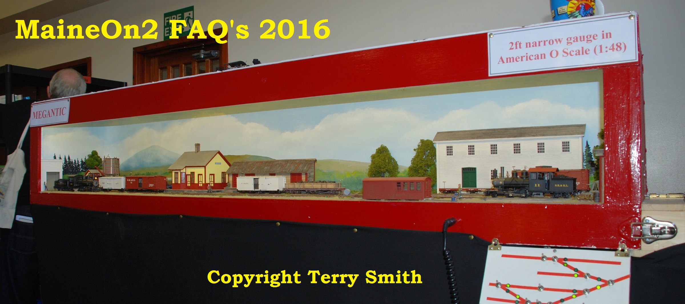
The left hand end section displays some typical Maine/New England icons such as a white painted clapboard church and and a white painted clapboard family farmhouse with front porch, but the space available precludes the usual attached barn structure.
The picture shows Richard “Momentum” Archer-Jones at the front operating position favoured by Bob so that he can talk to the public at exhibitions and also allow them to operate the layout.
A view of the layout control station situated in the left hand niche, showing the route selector panel, the two DCC throttles and the list of trains and train operating order on the back.
Spare Loco #8, loco #11, railcar #5, cream car 65, boxcar 75, boxcar 5, boxcar 125, pulpwood rack 213, Canaan Valley caboose 8.
Train order for New Sharon
Road 1 « « « « « « Loco #7
Road 6 Loco #23 » » » » » »
Road 2 « « « « « « Loco #22
Road 7 Loco #10 » » » » » »
Road 3 « « « « « « Loco #18
Road 8 Loco #12 » » » » » »
Road 4 « « « « « « Loco #2
Road 9 Loco #9 » » » » » »
Road 5 « « « « « « Loco #123
Road 10 Loco #24 » » » » » »
The right hand niche contains Bob’s introduction to the layout, explaining that the scale is quarter inch to the foot and the gauge is two feet (not commonly known or used in the UK) and presents a map of the location for the viewing public.
Bob has kindly provided a copy of the map shown in the niche.
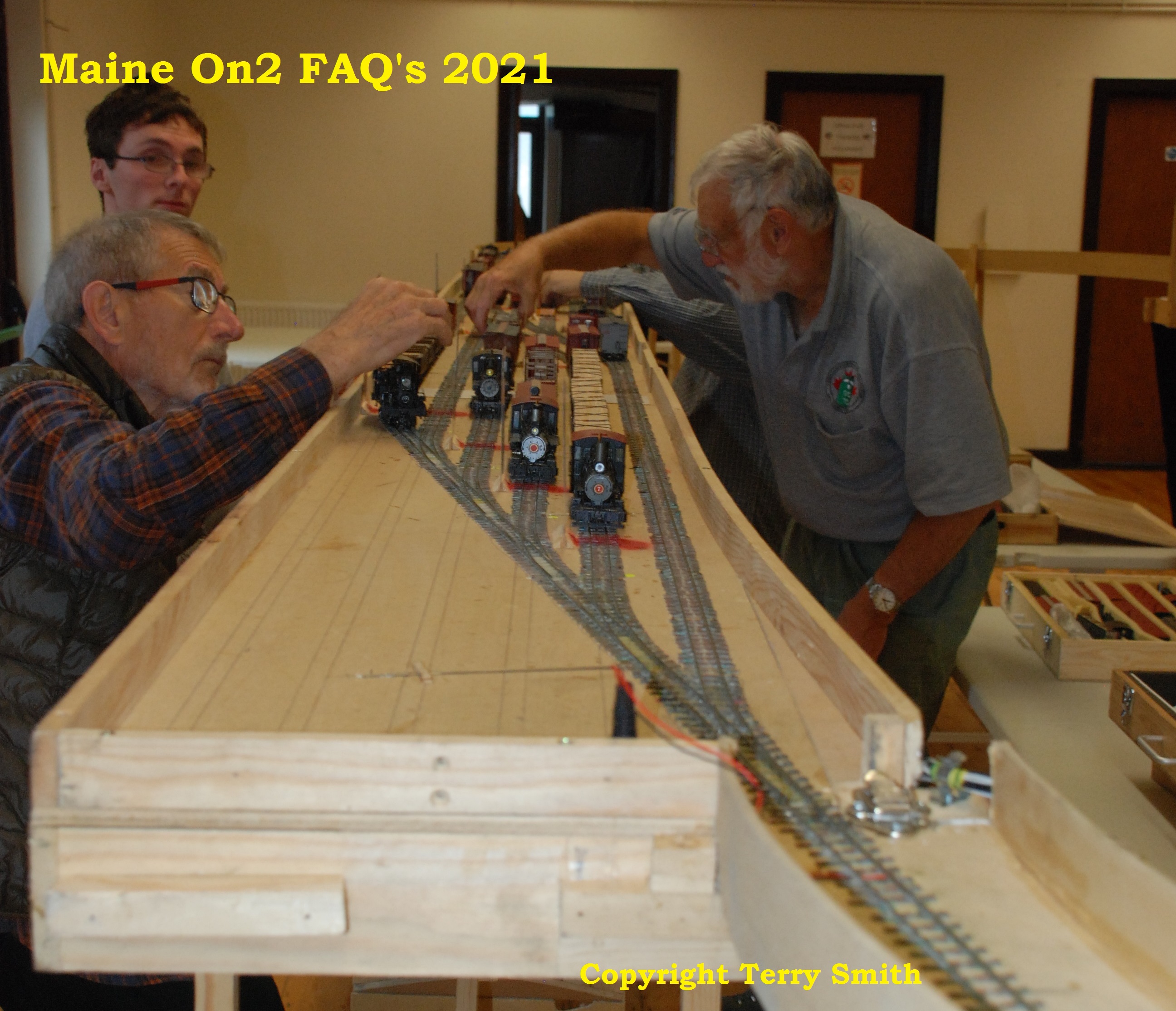
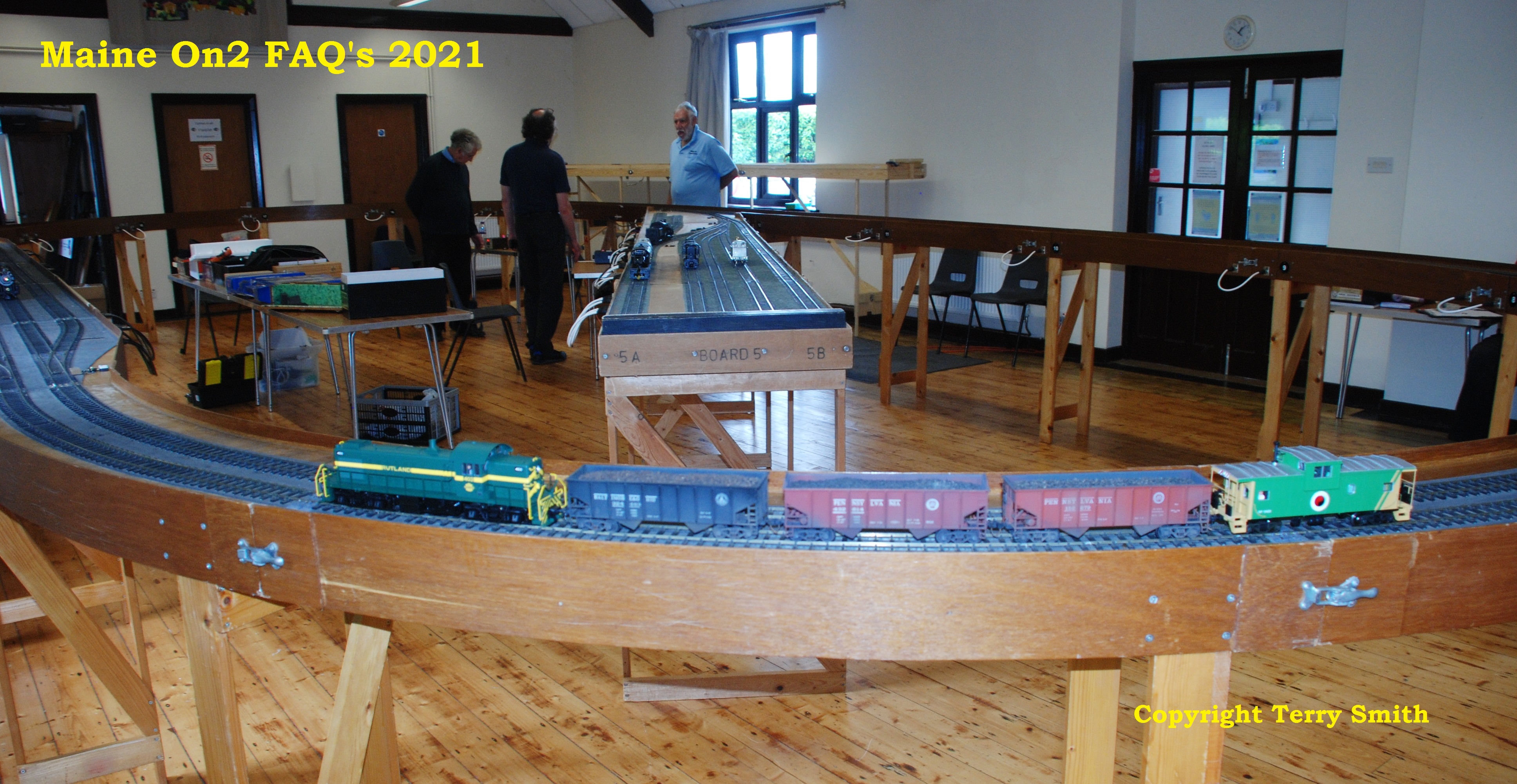
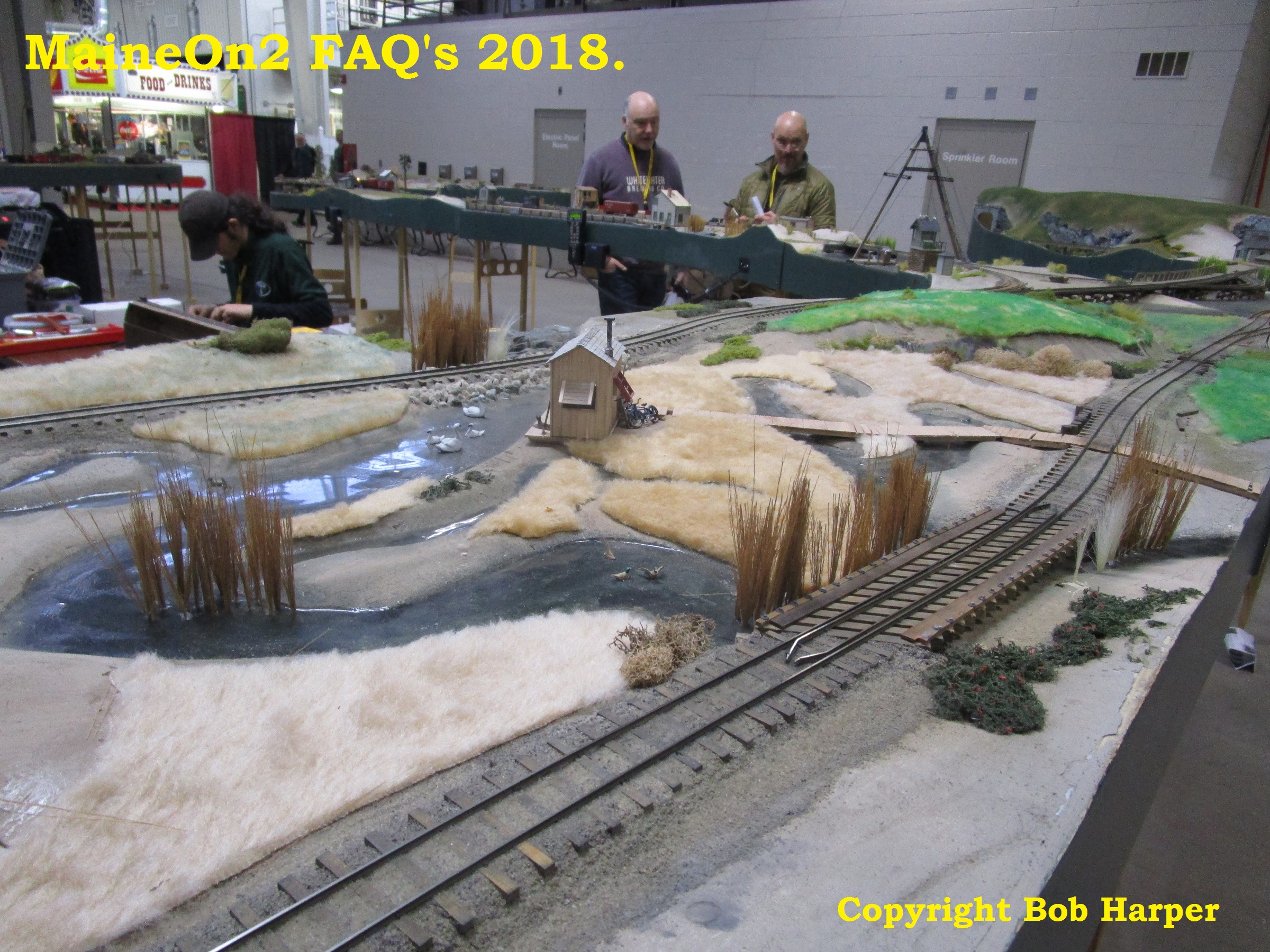
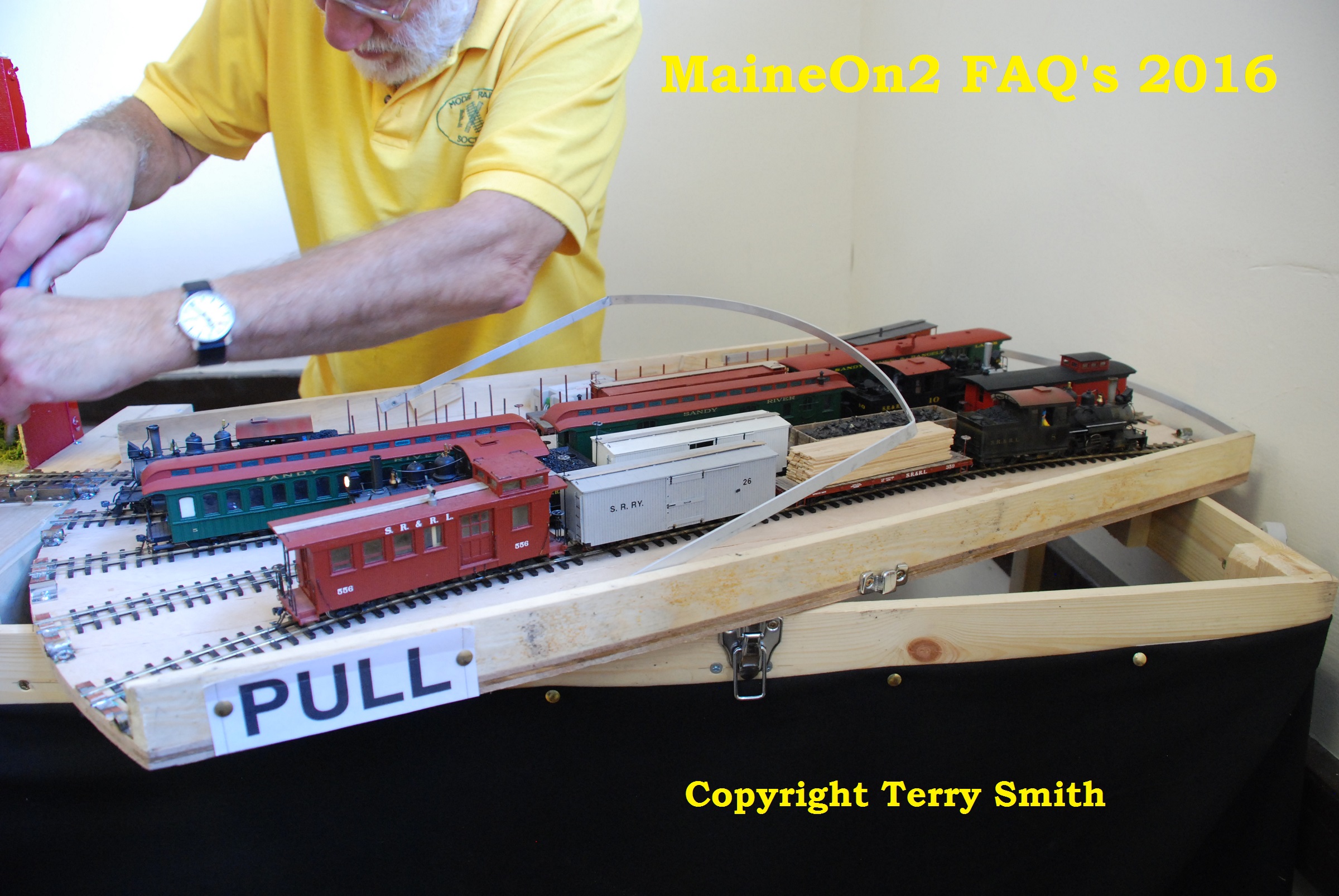
A view of the storage sidings at the back of the layout with the crew adding the trains from their travelling cases seen on the table at the right. The trackwork on these sections is handbuilt in situ using code 75 flat bottomed nickel silver rail soldered to glass reinforced pcb ties.
Crew members are John Pearson middle left with Lee Egginton behind. Bob Harper is middle right with Dave Egginton mostly hidden behind.
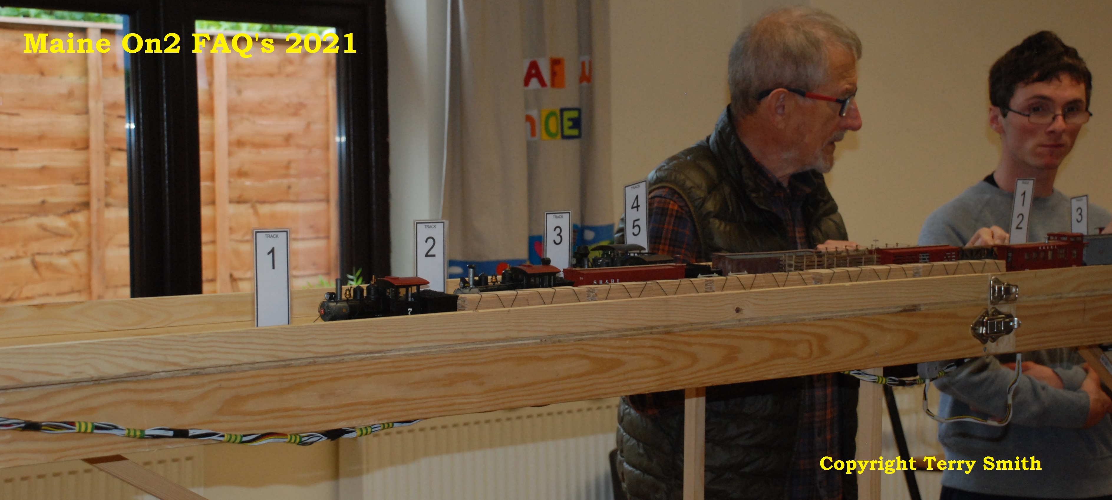
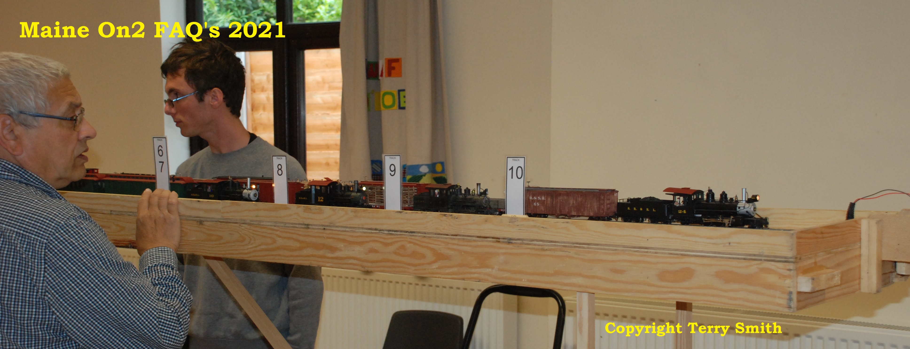
A view of the yard, now loaded with trains and with the marker labels showing the limits of each siding in position. The layout is operated from the front left corner, approximately the same as the camera position, and the labels are very useful when operating single handed.
Dave Egginton watches closely as the first train departs from the storage yard.
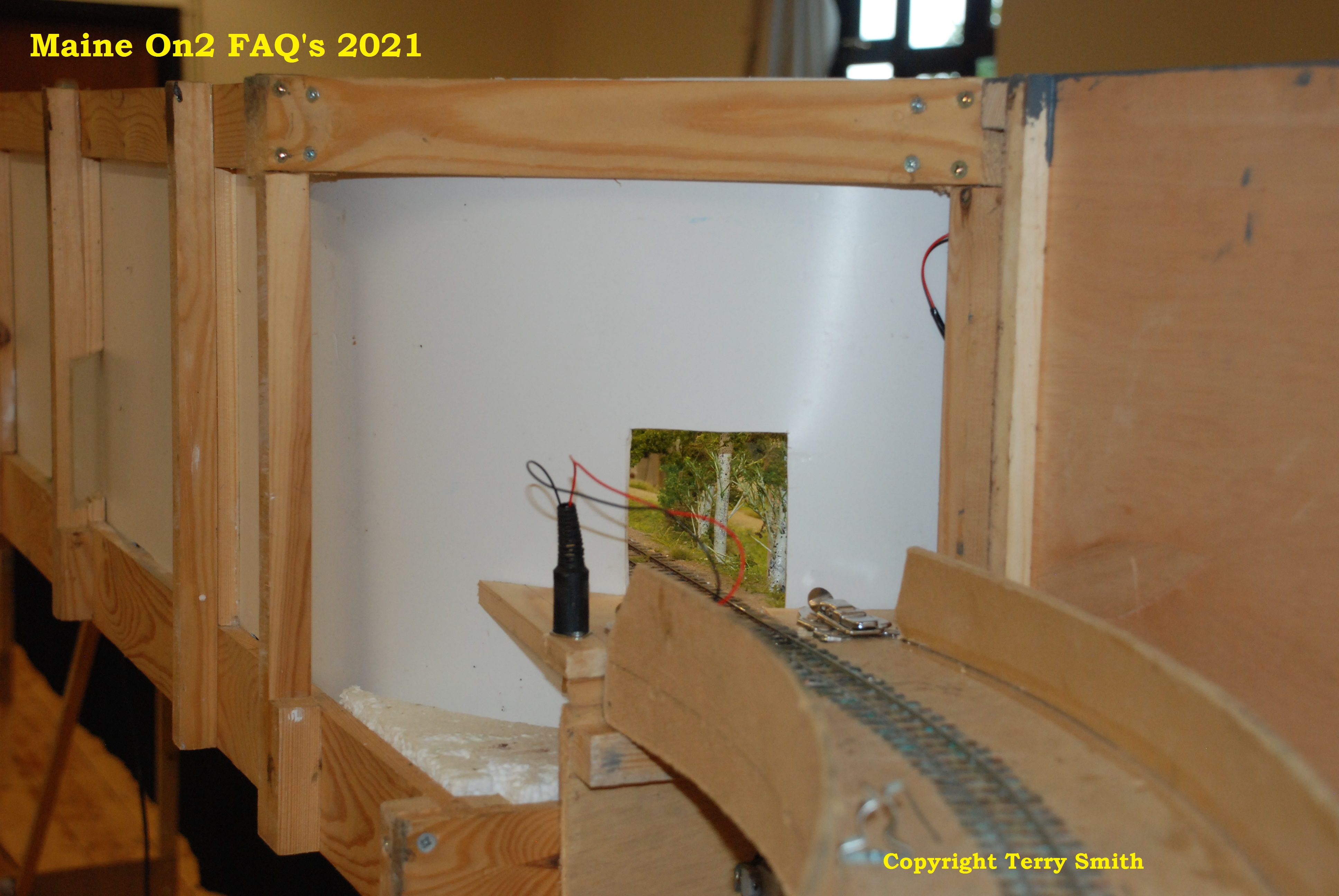
The trains enter and leave the scenic section through small holes in the curved backdrop. This shot shows the construction of the scenic modules and the attachment of the framework supporting the backdrop and top.
Part of the scenic section can be seen through the small hole. The small entry and exit holes are fairly easy to disguise or obscure. Take a look at the pictures of the ends of the scenic sections to see if you can spot these holes.
Getting pictures of the trackwork on the scenic sections is pretty awkward, even with “privileged” access. Shooting though one of the entry holes is an option and the above picture gives a view of the hand built track using Karlgarin code 82/7 nickel silver rail spiked to Mount Albert On2 sugar pine wooden ties with Micro Engineering small spikes.
Editors note: the Karlgarin rail used on the layout is a specially drawn rail in high nickel nickel silver with proportions to suit O scale narrow gauge use. Compared to standard US code 83 rails produced for HO track, it has a wider base flange and a wider rail head.
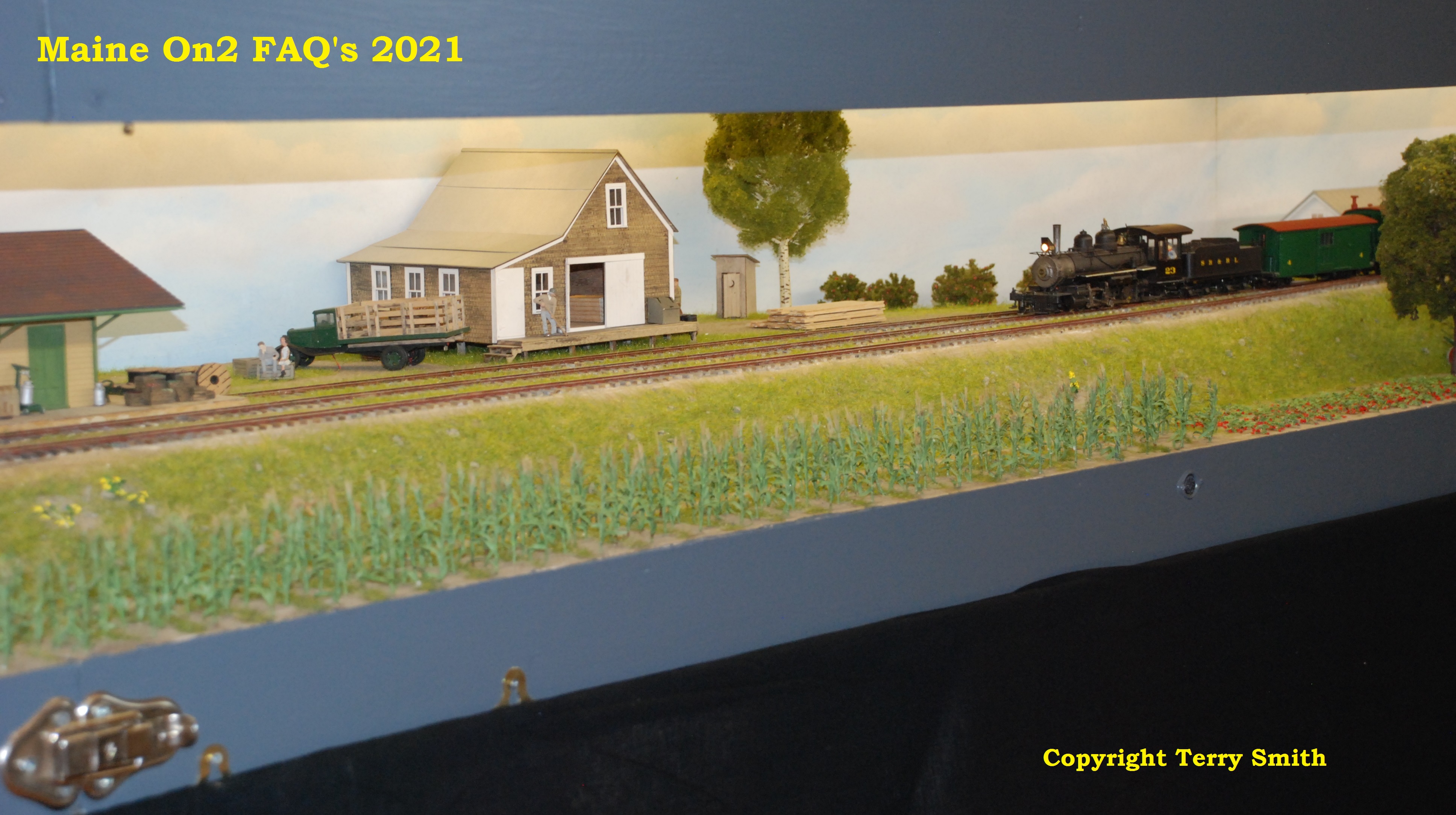
A closer view of the scenic section
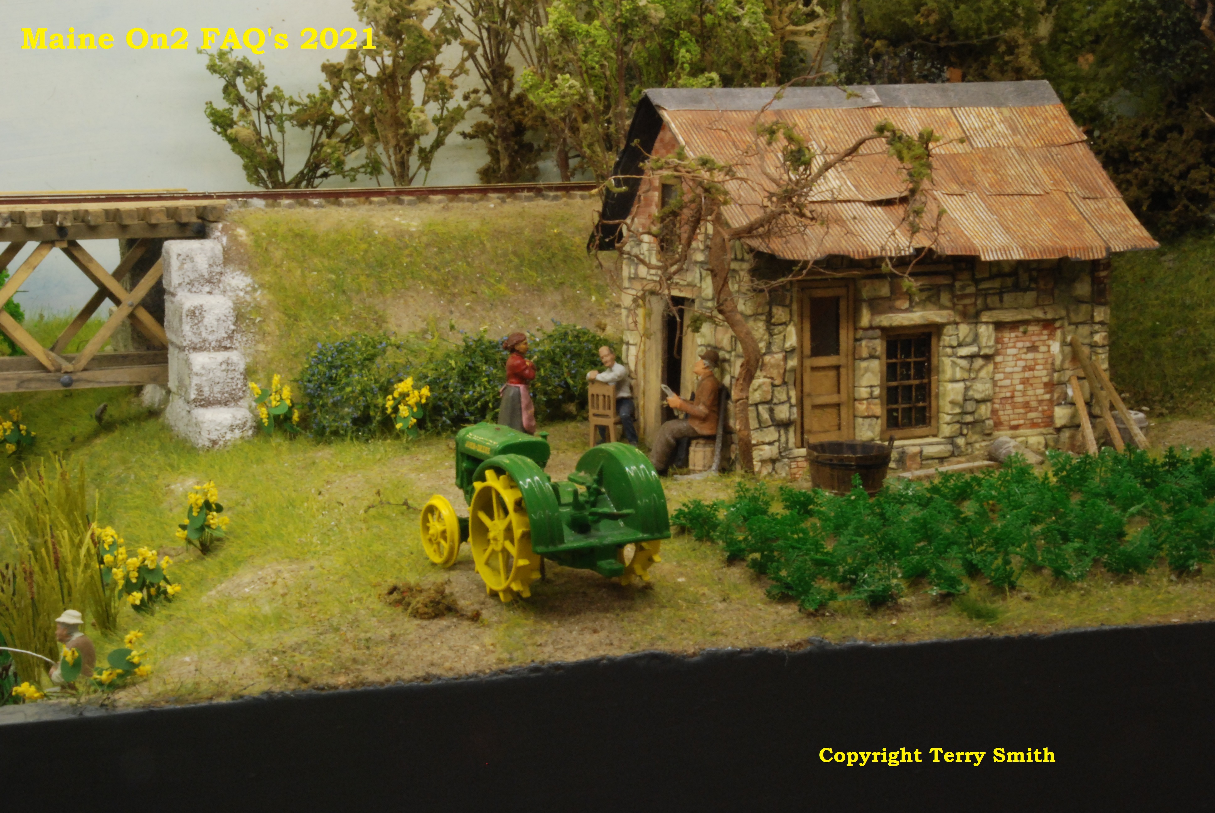
The stone farmhouse across the Sandy River.
The boat on the Sandy River.
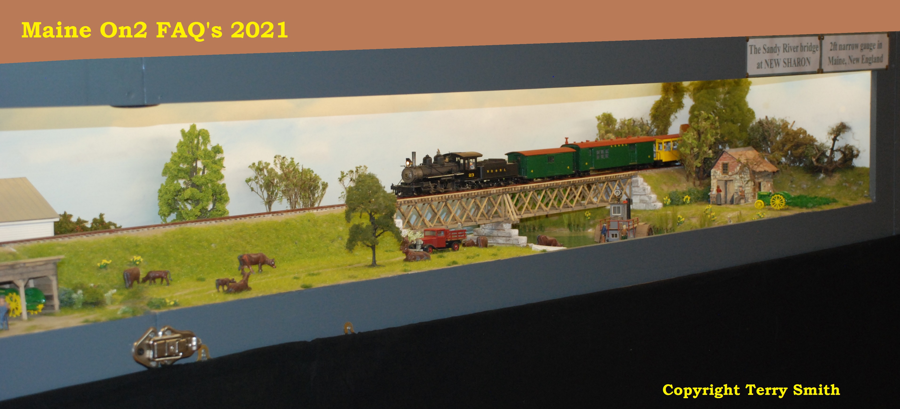
Train number 5 pulled by SR&RL #23 crosses the bridge at New Sharon.
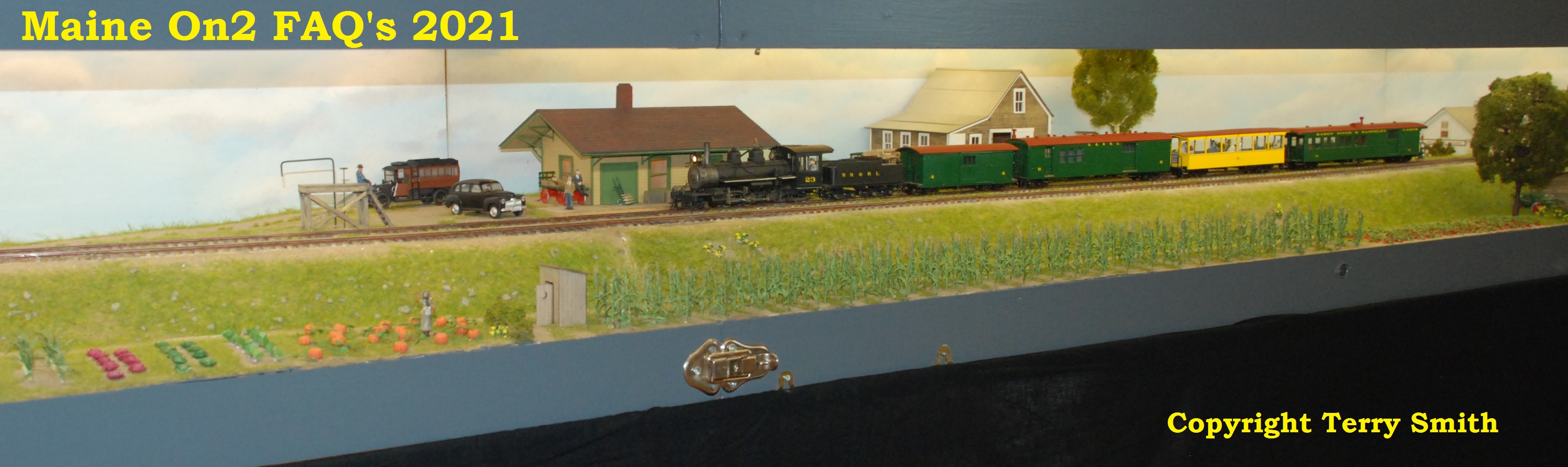
Train number 5 approaches the farm supply warehouse at New Sharon.
SR&RL #23 eases Train number 5 to a gentle stop outside the station at New Sharon.
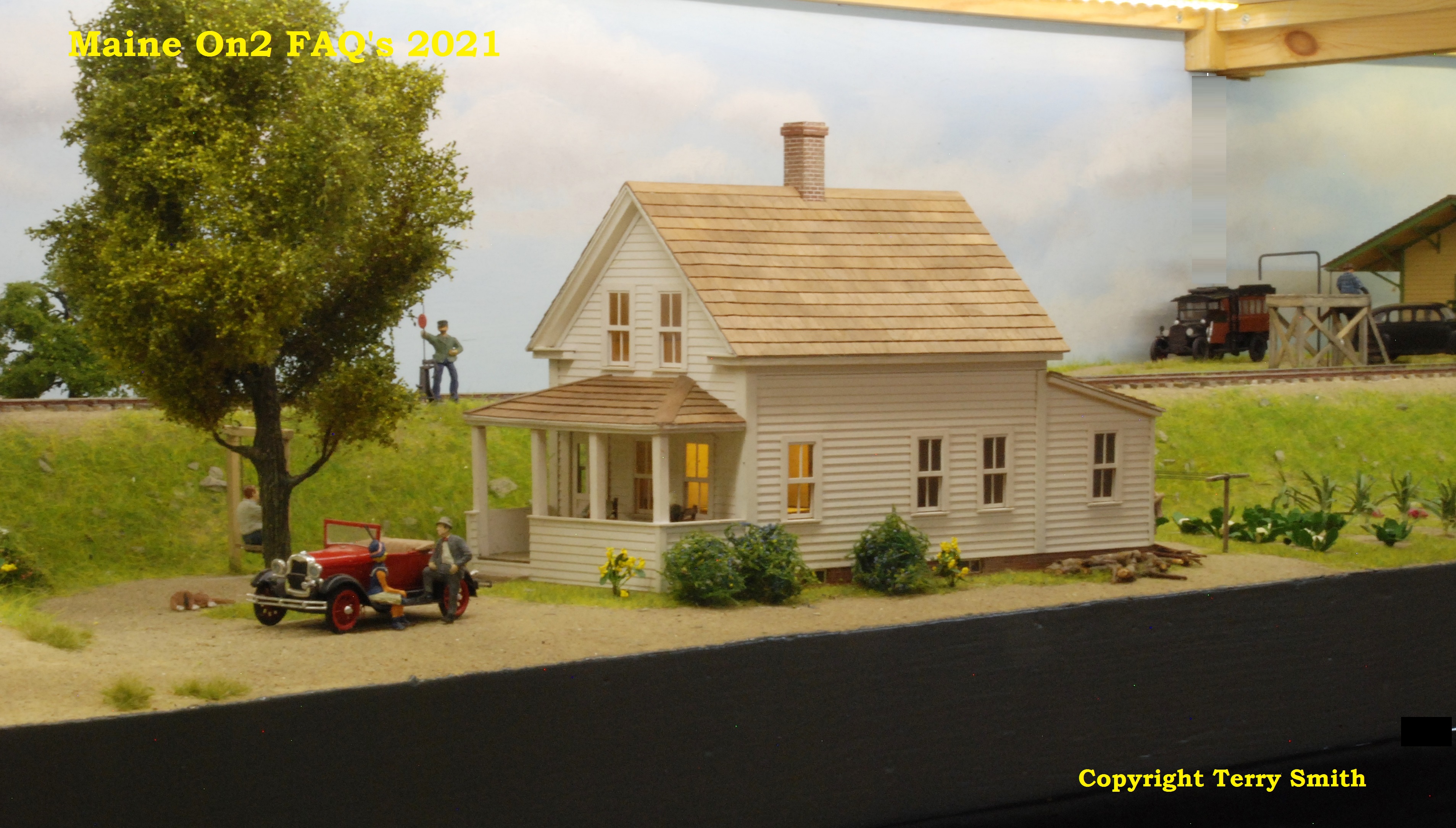
Beyond the station is a typical New England white painted clapboard family farmhouse with a front porch.
Opposite the farmhouse across the lane is another typical New England white painted clapboard structure – a church.
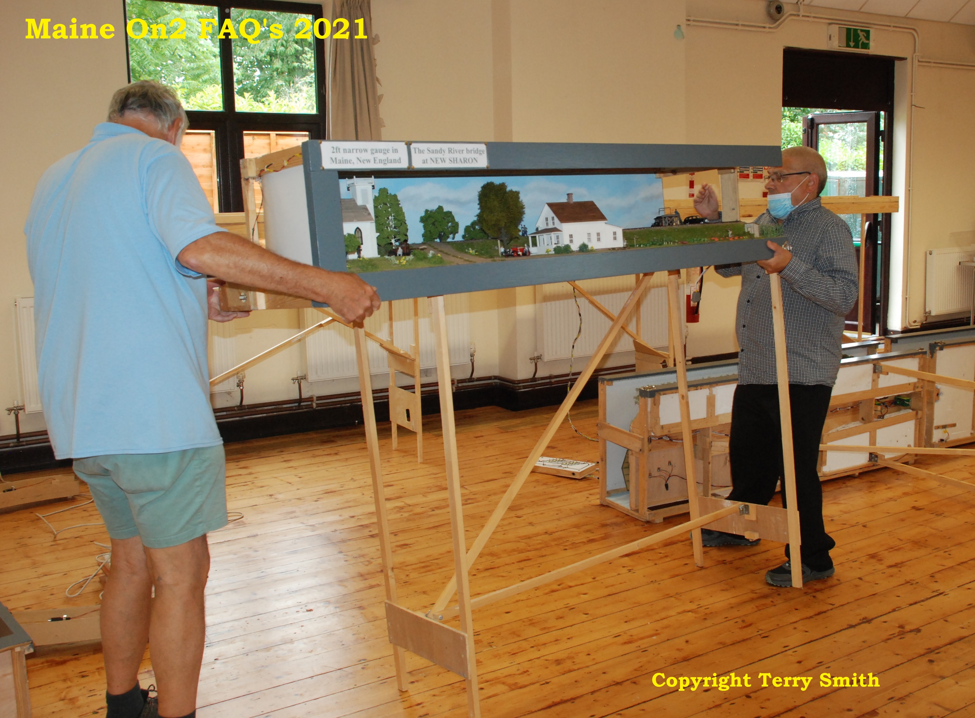
Transportation and erection of the layout
The storage, transportation, erection and maintenance of a layout such as New Sharon are major issues particularly when the home base does not have sufficient space to erect the layout and when the layout has not been erected or run for a period of time such as has happened in the UK, when Covid 19 restrictions have shut down the model railway exhibition circuit/circus for the last 18 months or so.
New Sharon had a booking to attend the UK 7mm NGA Exhibition in mid October 2021 at Burton-on-Trent. The following sequence of pictures show the “behind the scenes” operation to prepare the layout for its return to the UK Exhibition Circus.
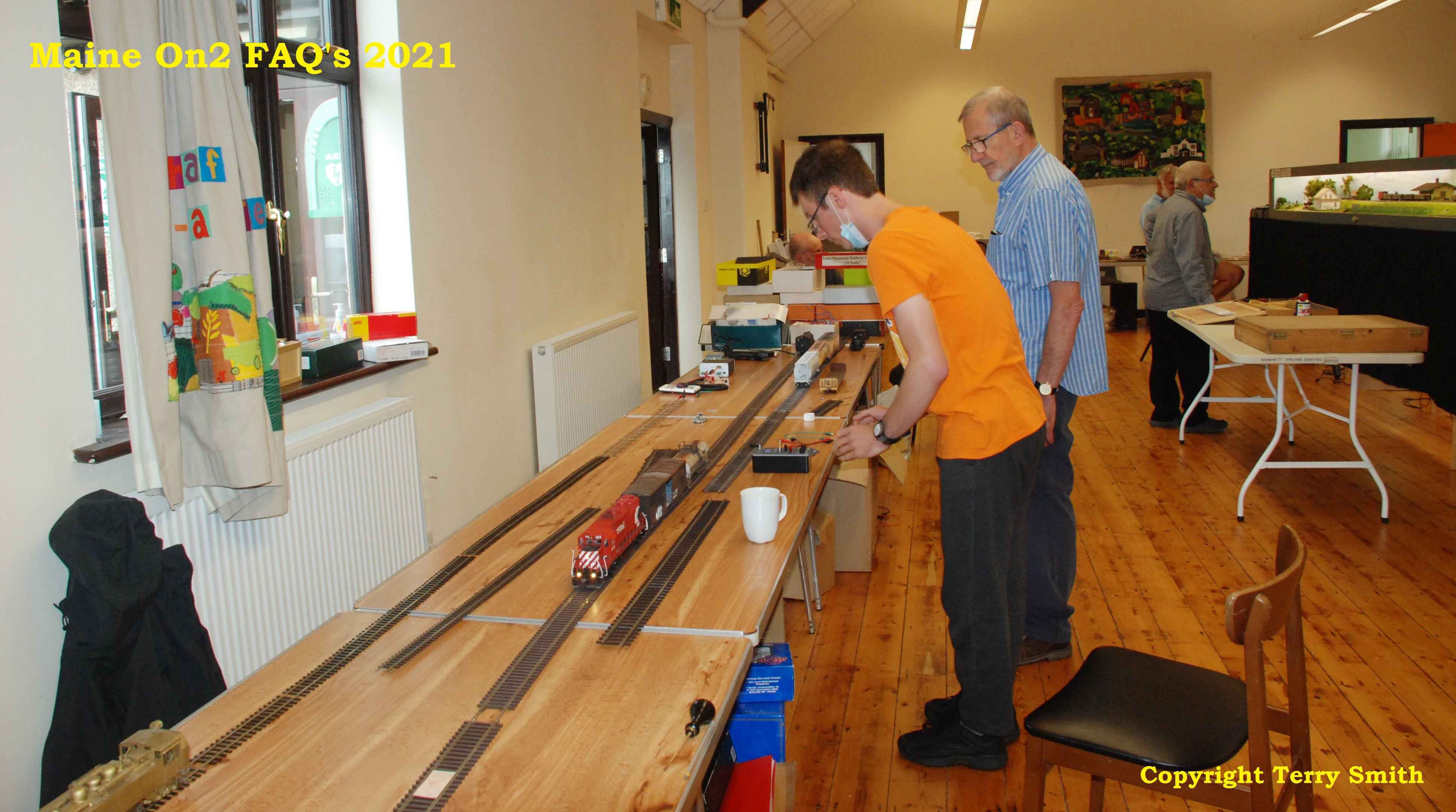
It started in early July at a US running session of the North Wales and West Cheshire O gauge groups meet in the Village Hall at Llanbedr, in North Wales. Bob (who is an occasional visitor to the American running days) turned up, as a visitor, to erect and test the storage yard sections of New Sharon in the restricted space left after the groups layout had been assembled in the middle of the room.;-
Terry Smith’s “train in a bag” in the foreground circulating on the groups sectional layout with Bob in the background with the New Sharon boards behind him, taking a break from trying to track some operation problems.
When I chatted to him, he said that he really needed to erect the whole layout to check the operation. We discussed various options, and I suggested that he looked into hiring the hall privately (the charges are very reasonable) and inviting local O gauge American narrow gauge and other specialist enthusiasts to attend to help defray the hall hire……..and in late August the first such event took place, followed by another in early October at which the pictures were taken.
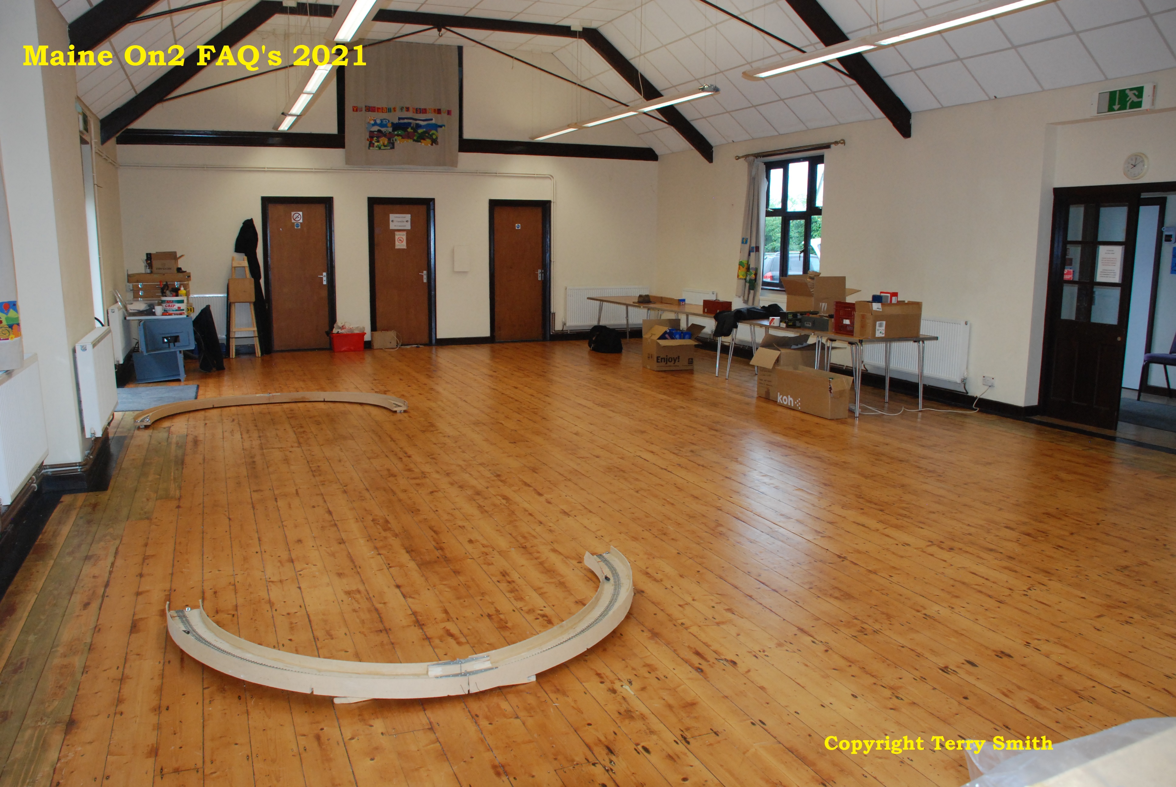
The Llanbedr Village Hall is not particularly big, but the space looks big when empty. In this picture the New Sharon curves have been unloaded and laid in place.
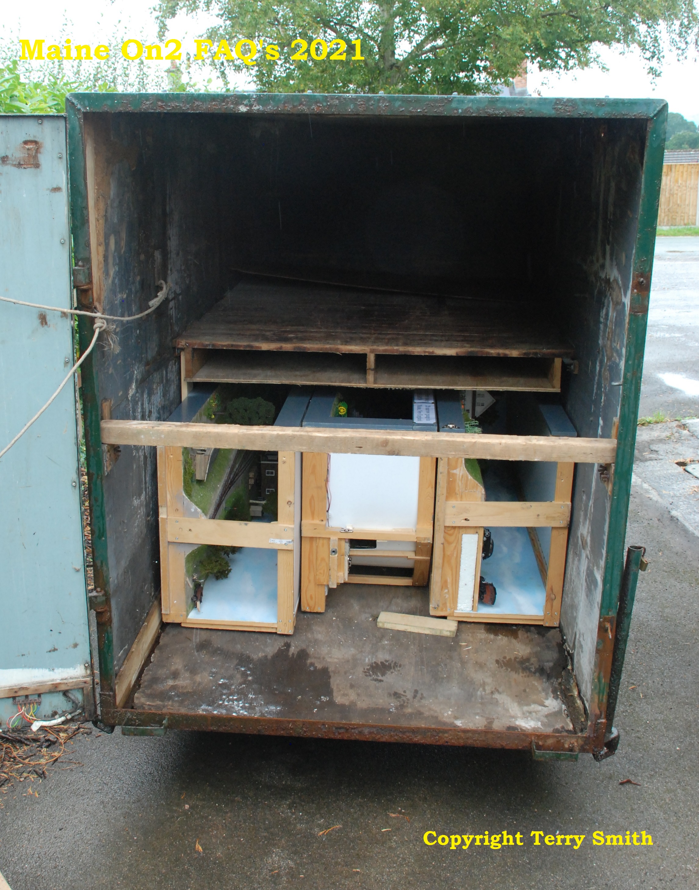
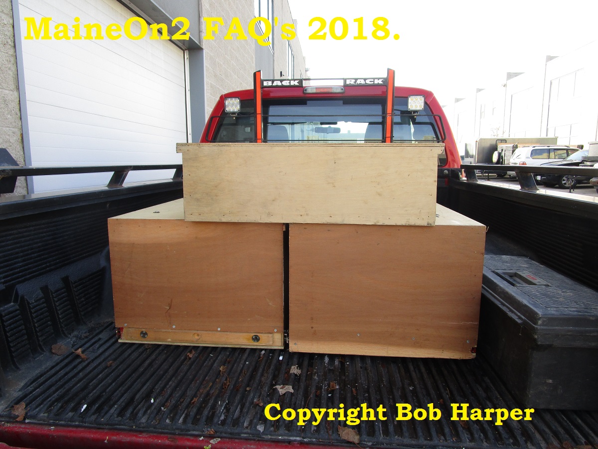
New Sharon is stored and travels to venues in a trailer. In this view, the top shelf of the trailer has been unloaded with the scenic sections yet to be unloaded.
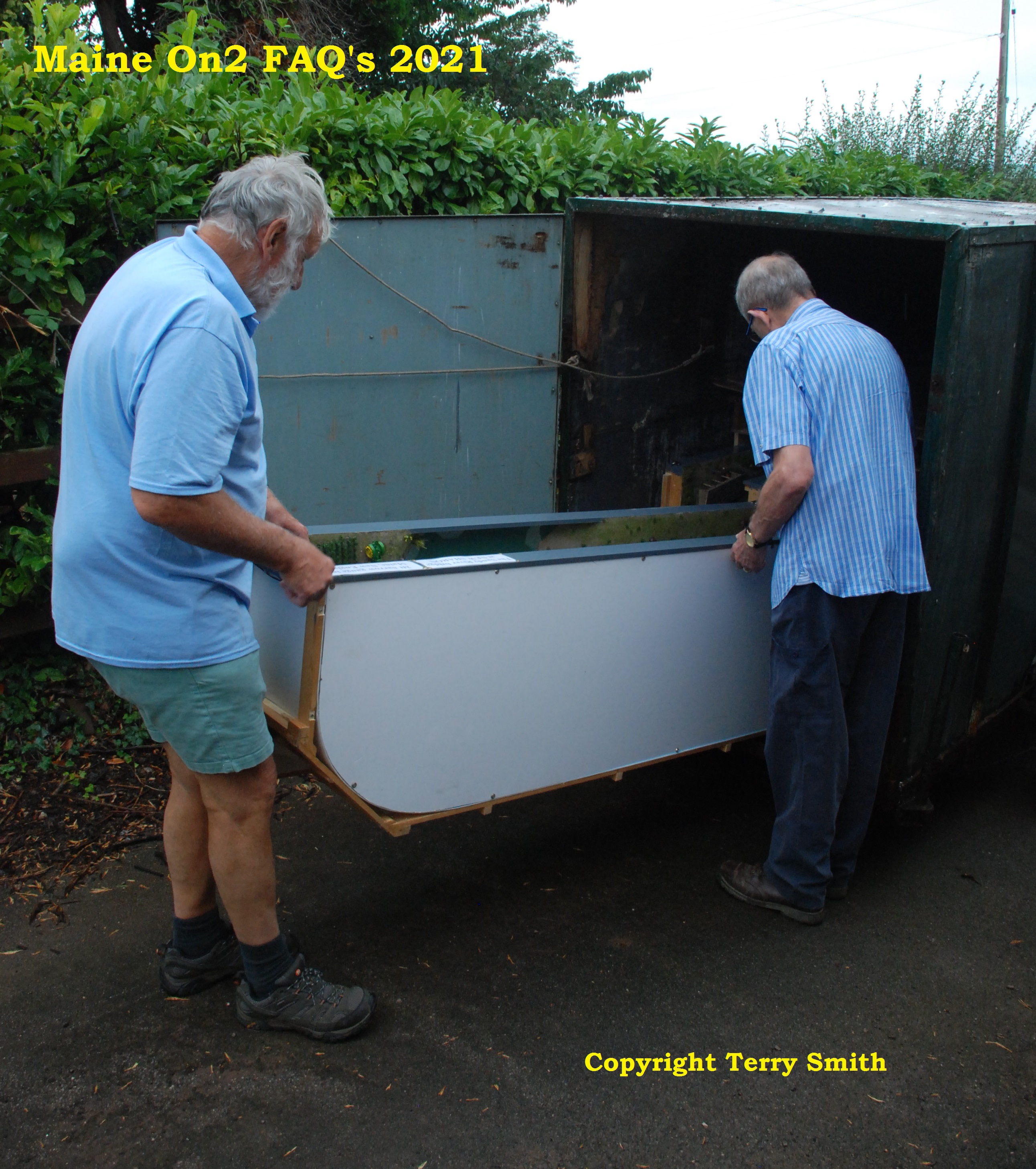
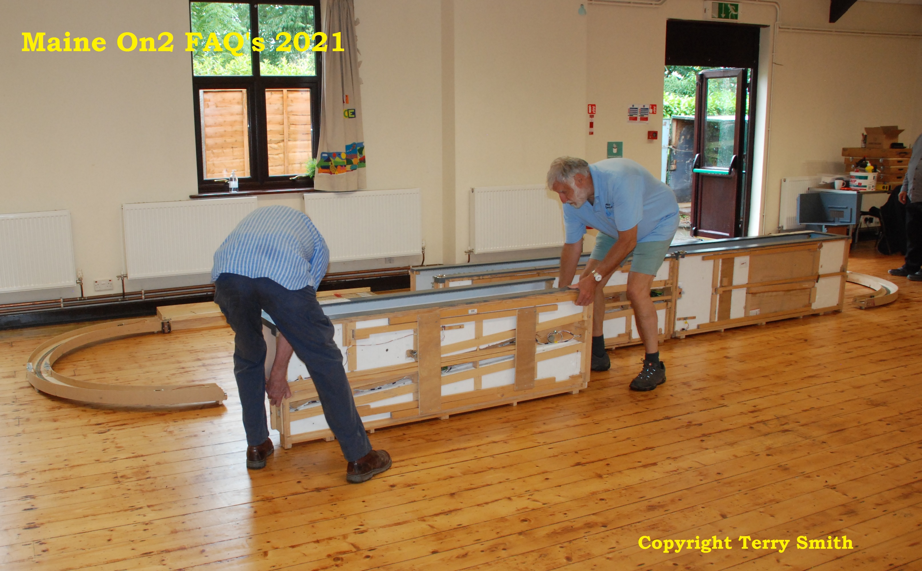
Bob Harper and John Pearson unloading the left hand scenic section which contains the bridge. This view shows the outline of the curved backscene which is continuous with no corners.
Bob and John bringing in the last scenic section and placing in approximate position.
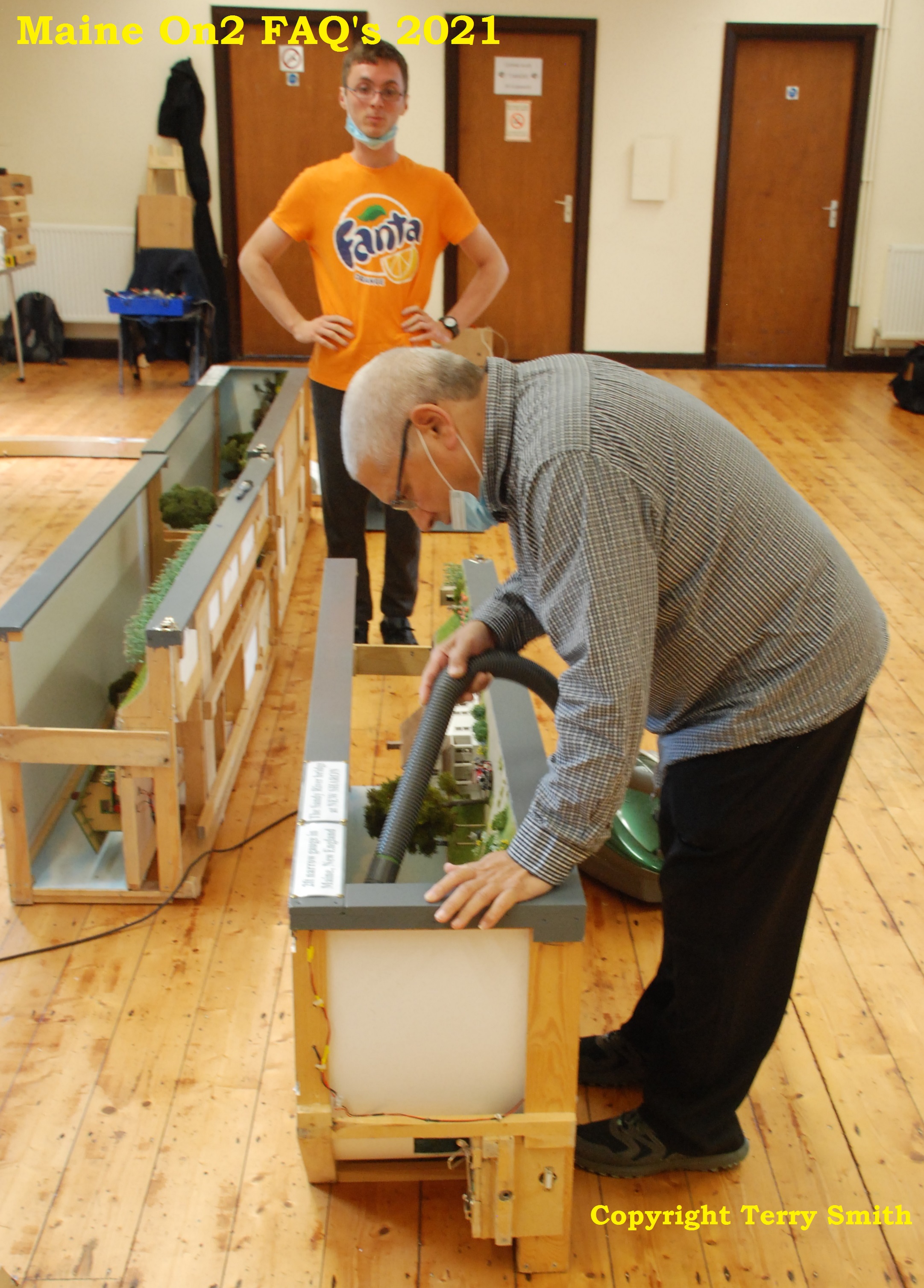
Dave Egginton did a really useful job of ridding the scenic sections of spiders and other detritus acquired during the long storage, watched by Lee Egginton.
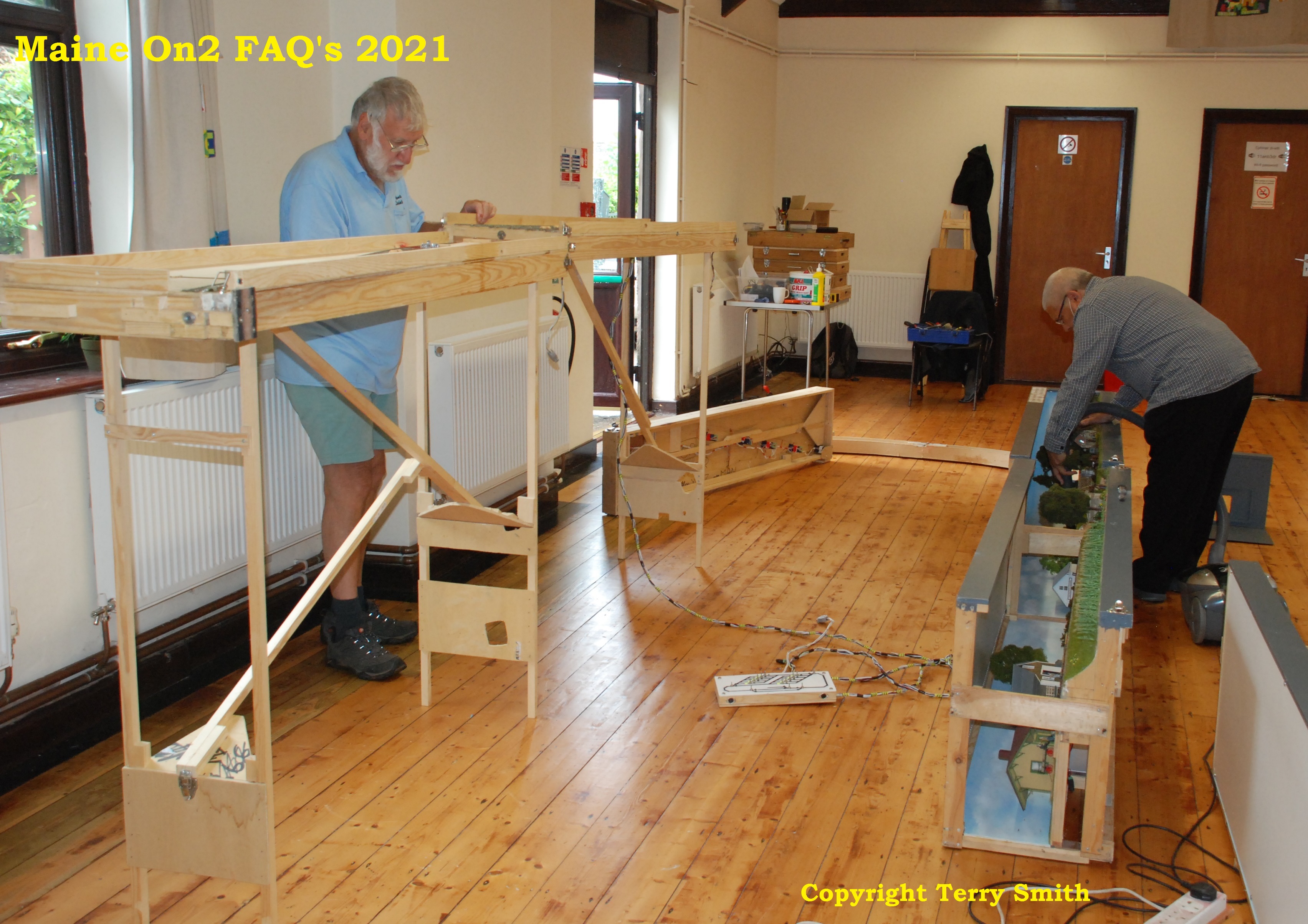
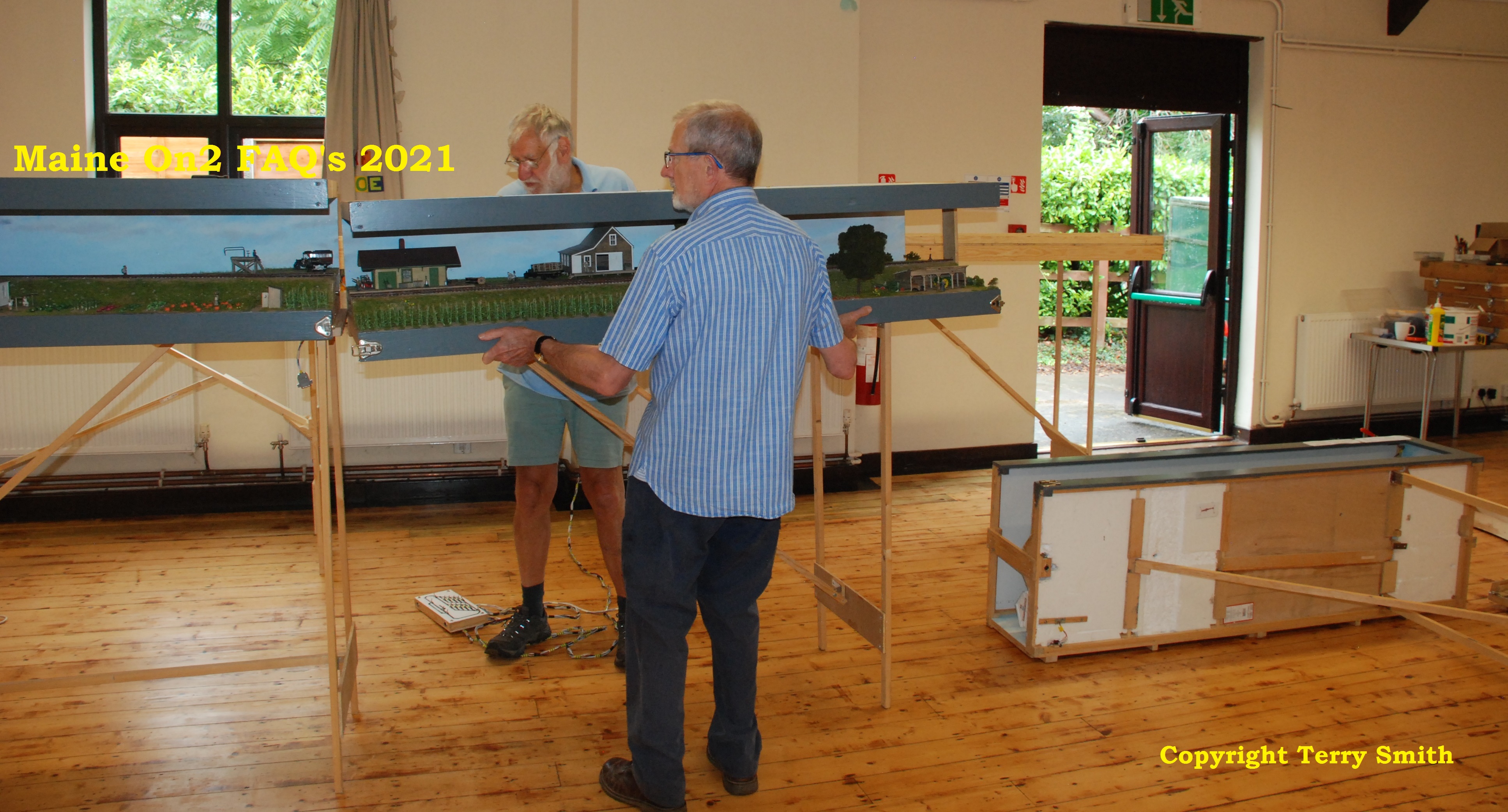
Meanwhile Bob and John have been busy in the background setting up the yard sections. Note that the first section has two sets of legs and can stand on its own, whereas the other two sections only have one set of legs each and must be attached to the first section to be stable.
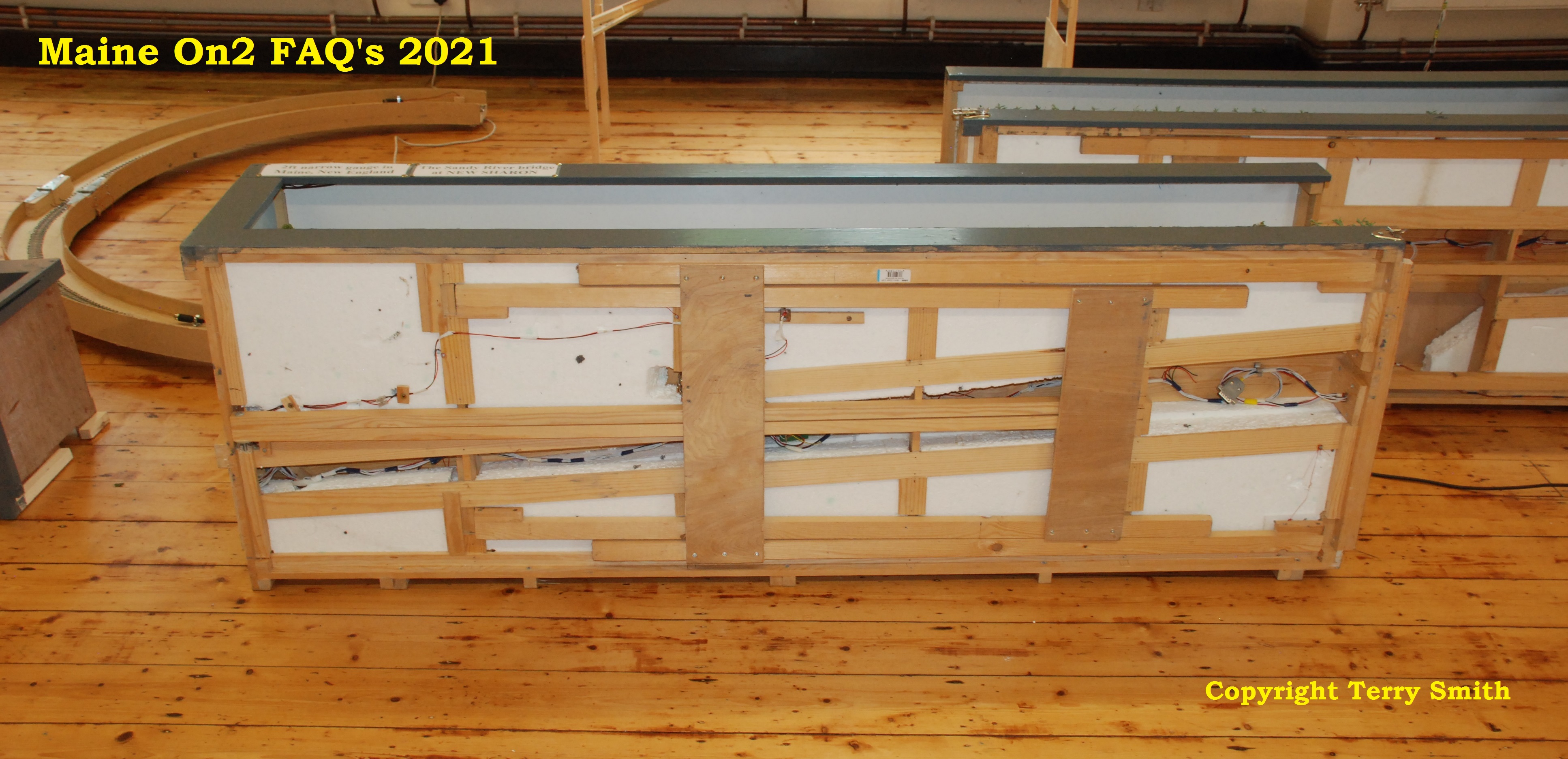
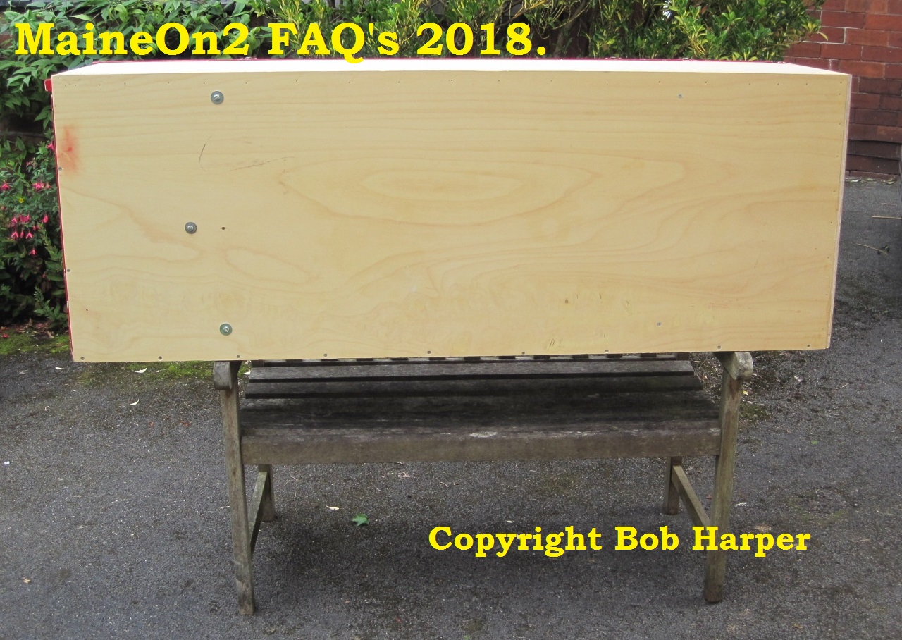
A closer look at the underside of the left hand scenic section which has two sets of legs and can stand on its own. Note how neatly the legs store.
The legs were extended while the section was on its back, and the section has been lifted and rotated into position with Dave Egginton helping.
John Pearson assists Bob in offering up the second scenic section (on one set of legs only) to the first section, while the third scenic section lies in the background, legs extended to be assembled next.
Voila! the layout is now assembled. Bob is adding a small G cramp to the top of the fascia joint to provide additional stiffness.
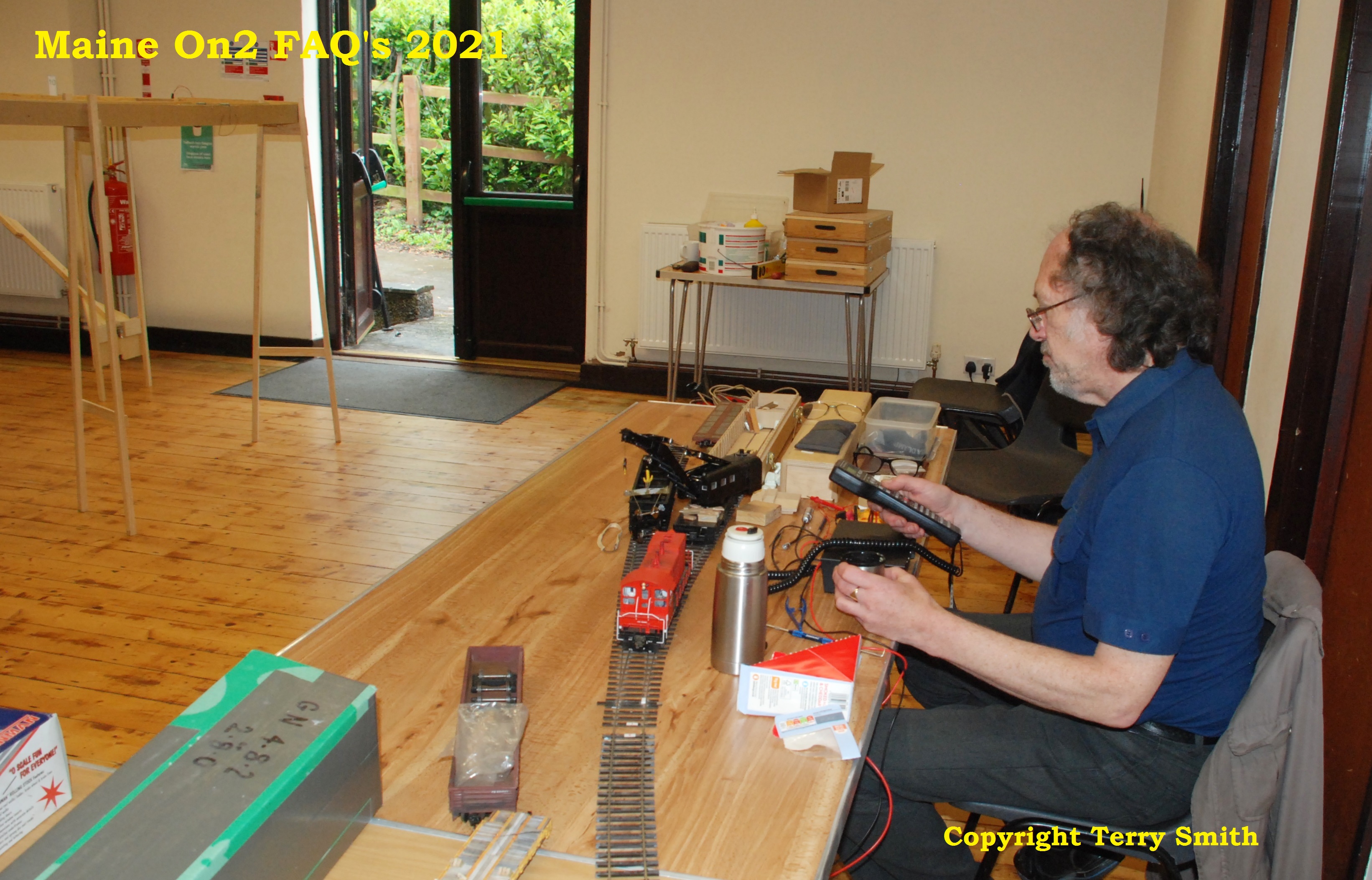
Supporting (some non Maine On2 – continue at your peril) activities in August
Richard (realistic operation) Archer-Jones playing with his newly acquired DCC fitted Lionel breakdown crane was among the invitee’s with special interest’s. Note the legs supporting the New Sharon end curve top right.
John Pearson, seen here in the blue shirt supervising Lee Egginton, was a major provider of support activities in August, bringing facilities to run standard gauge and On3 narrow gauge on DCC. Also demonstrating the Proto Throttle for DCC diesels, Protocraft and Kadee couplers and the operating possibilites of a Lance Mindheim style single turnout layout assembled from Atlas track on the table top. Note the Uintah 2-6-6-2 tank engine disappearing bottom left.
On the table along the far end wall Terry Smith provided running facilities for On2 and On3 under DC, Gaugemaster DC Momentum and PFM Sound System controllers. The 5 chime whistle with maximum reverb was a popular (and frequent) request as the system was fitted with a decent extension speaker. Jason Dickie had a lot of fun running the Maine On2 sound fitted loco’s and playing with the Sound System controls to adjust the sounds.
Jason arrived with a car boot full of goodies for sale and did a steady business. Terry acquired additional freight cars so now he has a longer train in two bags – and it looks better.
Terry also demonstarted the hill climbing and run back under gravity capabilities of his kit built On3 Kemtron Shay, which was built some 45 years ago when he and Jason were both members of the Bucks County Model Railroaders. Terry notes that it was Jason’s comments about the Maine Two Footers during the refreshment breaks at that group that alerted him to their charm.
Our regular viewers will know Bob Harper and his travels with his Maine style sections of his home layout. His most recent adventure has been to attend The Amherst Railway Show at the Great Eastern Exposition Fairgrounds in West Springfield, Massachusetts, in January 2018. In this post Bob has written and taken photographs showing how the module is packed to withstand the rigours of airfreight and other travels. Bob’s brother, Gerald, also a keen model railroader lives in Toronto, so it is natural for Bob to travel to Toronto, and then drive down to the US venues.
Before the Amherst show, Bob & Gerald took the opportunity to visit Trevor Marshall to view his home layout Port Rowan in Toronto;-
Bob Harper watches as a freight extra rolls out of Port Rowan, and later commented
“beautiful work, and very British in concept, but sadly not portable of course.”
Gerald Harper captures a CNR gas electric arriving at Port Rowan on train M233’s schedule.
Click here to view Bob’s Franklin module and here to view Bob’s Megantic module on new browser pages.
Click here to visit Trevor’s Port Rowan blog on a new browser page.
Click here to view the Amherst Railway show website on a new browser page.
FRANKLIN GOES TO AMHERST
After the relative ease of taking Franklin to the Narrow gauge Convention in Augusta, Maine in 2016, I got over-ambitious and planned to do it again, but on a larger scale.
There is an enormous general railway show at West Springfield, Massachusetts, every January, put on by the Amherst Railway Society; probably the biggest show in the US, with 8 acres of hall space and around 20-25000 attendees each year. I got cheeky and asked if I could come, and was welcomed with open arms! Fans of The Simpsons will know that they live in W. Springfield! So I arranged for the layout to come with me to Toronto in late January, and we headed off again over the border (a very tedious experience this time) in my brothers truck.
There was a mighty difference this time compared to the Augusta trip in August 2016; the temperature was -10 degrees Celsius and the Mohawk and Hudson Rivers were piles of ice – great blocks built up along both banks, and the whole way across in places. That said, we were very lucky with the weather generally, given how bad it could have been. Everything generally went smoothly at the show, the layout in particular running perfectly, though we had some difficulty with general arrangements and information. Nearly all the layouts and trade stands come every year, and they all know exactly what to do; so information for new exhibitors was very sparse. As a result, we never found the Saturday evening show dinner, though we didn’t go hungry! Packing up on Sunday evening went smoothly, and then another long drive back to Toronto.
This time, rather than bringing the layout straight back to the UK with me, I decided I would leave it, and the rolling stock, in my brothers workshop in Toronto. This means that I can also take it to the Canadian Narrow Gauge Exhibition at Schomberg, 30 miles or so north of Toronto, on Saturday 21st April, and the National Narrow Gauge Convention in Minneapolis in early September. Obviously this saves 2 round trips for the layout, and an awful lot of hassle, though I did have a bit more formality with Canadian Customs this time given that it was staying in the country for 9 months rather than 10 days. So now I’m back in the UK, with only exhibition appearances for my Great Western standard and broad gauge layouts until the Autumn.
Is it worth doing? Financially obviously not, but as an experience of a type of show completely different from a British one, then definitely yes. Although there were thousands of people there, the interest seems to be in the trade stands rather than the layouts. There were rarely more than 1 or 2 people watching any of the layouts, but those who did watch Franklin were usually engrossed for a long time. In particular, everybody was fascinated by my full turntable fiddle yard, where complete trains are turned ready for their next trip. Some people use a simple traverser, but a full rotating yard is a completely new experience. There were a good number of people manning the Maine preservation societies stands, and they made up a large part of my audience. It seemed wonderful to them that their favourite lines could actually be modelled in a meaningful way, with smooth and reliable operation and many of the features of the Maine 2 footers modelled in such a small space. So it was greatly rewarding to present such a novel way of modelling in the land of the actual prototype.
Bob Harper, February 2018.
One of the scenic boards being boxed up
Boxing up the fiddle yard, lighting fascia, and curtains
A snug fit in the Ford Mondeo Estate for the trip to the airport.
The whole layout after collection from Canadian Customs on the other side of the pond.
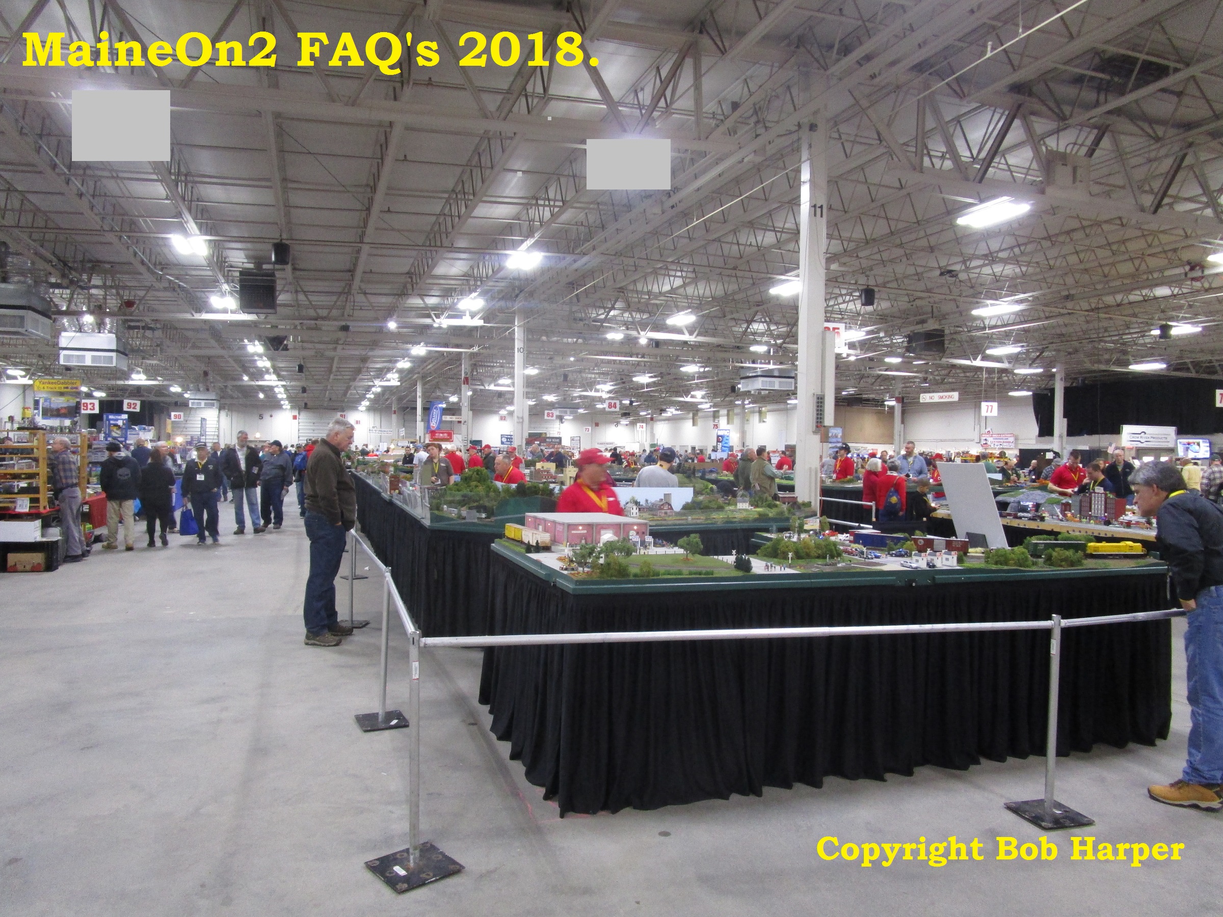
The layout unpacked and set up in one of the 4 halls of the Amherst Railway Show at the Great Eastern Exposition Fairgrounds in West Springfield, Massachusetts. Note that most photographs have not been cropped and edited purposely in order to show the vast amount of space at this show and venue.
A local New Englander has a go operating my New England layout!
Although there were 17000 people at the show, it was never crowded in our hall, but there was a steady trickle of Maine 2 foot fans from the WW&FR and SR&RL Museum stands coming round to see, and all seemed amazed that such an interesting layout could be fitted in so small a space, and that everything ran so well, with smooth, slow shunting. They were also all amazed by the fiddle yard, especially when they realised that it could turn the whole trains round 180 degrees ready to go out again! So while a lot of cost, work and stress was invested getting Franklin there, it seems to have been a worthwhile educational effort, as it was a completely different concept from all the other layouts there.
One of the many modular layouts in the show; this one shows the fairly common scenic mismatch of adjoining boards.
However this vast layout has a properly planned gradation from scene to scene. Any Exhibition Manager would be envious of the space available!
A general shot showing the staggering size of the show. Remember that this is only one of four halls, though two of them were smaller.
Scenes from an On30 modular layout. The standard of scenic modelling was exceptionally high, though some of the physical details are a little unlikely! Sadly this layout suffered from a seeming inability to run any actual trains reliably, a common fault with this type of communal project.
This 0-4-0 2ft gauge loco from the Edaville Railway was in steam outside the main hall, though restricted its action to regular whistle blasts.
Click here to view a short YouTube segment showing this loco at the Amherst Railway show on a new browser page.
I was surprised how quickly we were able to get the layout dismantled and boxed up again ready for the open air trip back to Toronto. Normally it travels in the back of my car, with no extra protection. I’m glad we did not try that this time, as we ran into a blizzard just after we re-crossed the border into Canada.
All the rolling stock and ancillaries came in these crates, which also braved the elements in the back of the truck. The crucial piece of equipment is the power converter, which I bought in Canada. This converts European 230 volts to N. American 115 volts, or vice versa in my case. So everything on the layout (lighting, for example) was operated at its normal 230 volts. This seemed easier than trying to rig up temporary 115 volt lighting, power transformer etc. It worked very well, though got pretty warm after a full days operation. None of my UK light bulbs got broken on the flight either, though I had taken several spares just in case.
The next trips;-
The baseboard boxes and most of the rolling stock have been left in Toronto, so I can go back and do the Canadian Narrow gauge show at Schomberg on April 21st, and Narrow gauge Convention in Minneapolis, 5-8 September. I will then bring everything back finally.
Click here to view the Schomberg show site on a new browser page.
Editors note, dated 28th January 2022: this topic was originally written and posted at the end of December 2016 and and a small part of the content has now been “overtaken” by the NMRA updating their information. For the sake of historical continuity the original posting will remain available to view with small modifications (change of tenses and links etc), and the recent NMRA update will be added as a standalone section at the end.
Parallel track spacing can be a problem for Maine On2 (and other scales) layout builders at the design stage, particularly if they need to shoehorn a design into restricted space, as there is not a lot of information around for guidance, but here’s what we have found.
The NMRA Standard for model railroad parallel track spacing was S-8 which has been discontinued. The general view of the Maine Two Foot modellers was that this standard is not particularly helpful as it depends upon interpretation and interpolation, but still does not give clear results for On2. This was so eloquently put by Yahoo! group member Hilary Smith very many moons ago:-
In my reading so far, I have either not come across spacing discussions or have overlooked them. Looking at NMRA S-8 Track Center Standards for Class II (small four-wheel truck diesels; small steam; old-time, logging, branch line rolling stocking stock) O scale standard gauge puts tangent track at 3.75″ (or 15 scale feet) apart, and for a curve of 41.5″ radius, 3.8125″ apart. For On3, tangents are 2.75″ and for 41.5″ radius, 3.375″, proportionally much wider spacing in curves relative to tangents than in standard gauge. Comparing On3 tangent spacing with standard gauge shows that the track centerlines are a full 1″ or four feet closer together, but on curves only 0.4375″ (or 1.75 feet) closer together. So, are On2 cars no skinnier or longer than their On3 counterparts meaning that On3 spacing standards are a good choice? Or should the centerlines be closer still? Thanks for any observations, experience, or advice.
Hilary Smith, Northern Virginia
The post got two replies;-
Terry Smith: The Maine two foot passenger cars can be longer than was common on three foot gauges, meaning that models of Maine cars “cut the corners” more than the equivalent three foot lines. The controlling dimension is the truck centres. I think that three foot narrow gauge cars are slightly wider in general than two foot, but not sufficiently different to make a difference modelling wise for track centres. ie using the On3 data will be OK for On2.
Trevor Marshall: You asked about spacing between tracks on tangents and curves for On2 layouts. I think it’s safe to say, as Terry Smith suggested in his reply, that passenger cars are the critical equipment for curves. Therefore, if you have such a car (SR&RL – not, say, Monson, whose lone passenger car was much shorter), you could do your own testing:
1 – lay a minimum radius curve on a surface on which you can draw with a pencil. You can either spike down a piece of On2 flex, or just a pair of rails, directly onto, say, a 1×6 piece of pine.
2 – put the car on the track.
3 – holding a pencil at each end of the car on the outside of the curve, roll the car along the track so the pencil draws a line on your surface
4 – repeat holding a pencil at the midpoint of the car on the inside of the curve.
5 – measure the offset between the track centerline and each line you’ve drawn.
Note that the pencil line will be slightly offset from the edge of the car – that’s built-in clearance for you. If you don’t yet have a passenger car – or don’t want to use that nicely painted model as a marking device – you could always cut a passenger-car-sized piece from styrene or wood (doesn’t have to be exact, but should be at least as large as the car is, corner to corner), add some bolsters from styrene strip under it at the proper locations, and screw some On2 trucks to it. You could even add pencil holders at each corner and in the middle if you like. Build two of them and you can check clearance on the layout before running your real models through. Heck, even add vertical pieces at the ends and in the center to turn one into a clearance car for bridges, buildings, holes in the backdrop, etc.
That’s curves for you. For straights, I have two standards: For transfer tracks, freight platforms, or other places where cars will be spotted adjacent to each other or adjacent to a structure with the intent that plates be dropped between them for the transfer of goods via hand-trucks or strong backs, I use my widest pieces of equipment to lay the tracks as close together as possible without sideswiping. For other places, I’ve spaced tangent track on 3″ centers. This is way more than the minimum spacing required, but it looks right to me – narrow gauge yards tend to have a spare, open feeling to them, and 3″ spacing allows for an O scale figure to stand between cars on adjacent tracks without getting sideswiped. Remember, the minimum is not always the best.
Hope this helps. – Trevor in Toronto
Some time later, the question was asked again, and this time the replies included references to the Maine Two Foot prototypes and other modellers’ experience.
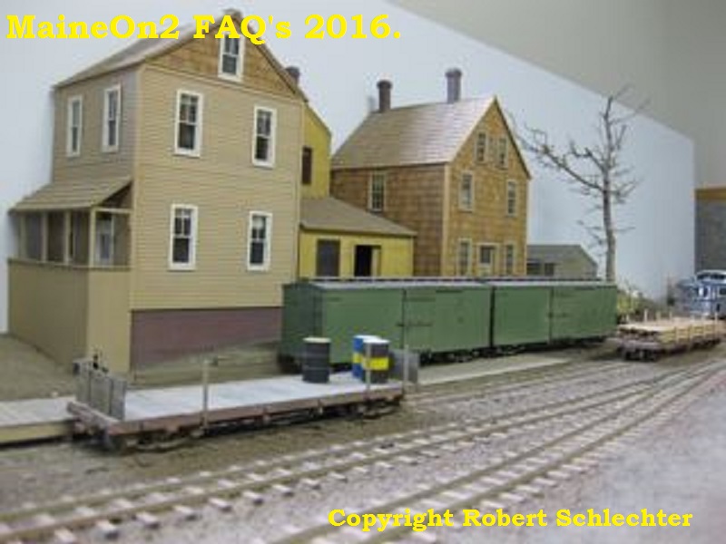
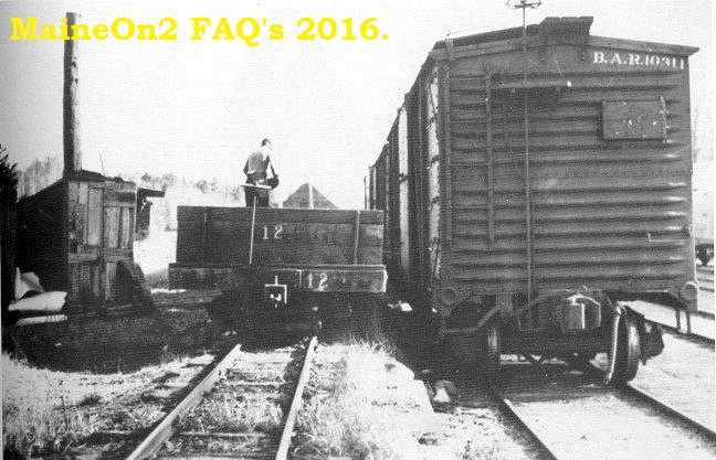
Bob Schlechter: Scaling from the prototype photo above, taken at Bridgton Junction, gives approximately 8′ 7″ to 8′ 9″ as the center to center distance of the two foot trackage to the standard gauge trackage. The photo was taken from the roof of a standard gauge box car looking downward at the trains and trackage giving a good vantage point.
Bob Schlechter: on my Kennebec Central diorama (above) I used 8 1/2 scale feet center to center. Looks good for prototype spacing but if one is going to do lots of operation and switching you may want it wider to allow for full size fingers to be able to reach in between cars!
Terry Smith: “I used 2½” spacing for straight parallel tracks widening to 2¾” around the curved sections (36” radius) on the Reading iteration of my P&SR (pictured above). I added the extra bit of clearance around the curves because I had a passing loop cum staging tracks that were bent round a 90 degree corner in parallel.
I do not recall having problems with access for manual uncoupling (using a Rix wand for my Kadee’s) or with interfering overhangs/underhangs with the longer rolling stock (coaching stock and Bridgton 34 foot freight stock) or locomotives like the large Forney’s, (B&SR/B&HR #7 & #8), or SR&RL #24 using these values.
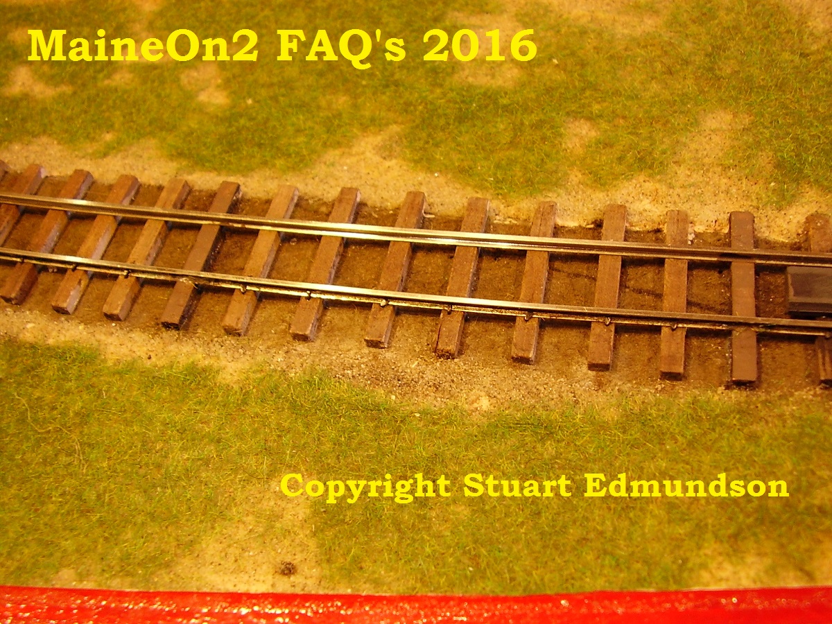
Bob Harper: I use 3″ spacing on my On3 tracks and 2½” on my On2, which reflects the difference in width of the real rolling stock – 8′ on the 3′ and 6′ on the 2′ lines. Looking at Franklin on the FAQ’s will show how this looks.
Editor: see the picture above of Bob’s Franklin module where the slight out of focus plus lighting highlight the tracks. To view more pictures of Bob’s Franklin module on another browser page, click here.
Bob Harper continues: Obviously the throw-over of the long On2 coaches is important, but I have found that the critical dimension is the cab on SR&RL #23. This is far wider than anything else (apart from a snow plow?), and my mistake of having the driver leaning out of the side window made clearances even worse! He has since been repositioned.
But another factor to bear in mind is the sense of proportion of the whole scene. Unless we are very fortunate with the space available, we inevitably have to fore-shorten out scenes, and trying to keep a prototypical width while losing the prototypical length can lead to the eye perceiving the track spacing to be too wide. In order to keep the overall scene in proportion, it may be necessary to slightly reduce the track spacing from prototypical standards.
Trevor Marshall: I like the generously spaced look of the Maine Two Foot yards, like in the picture below of Bridgton on the B&SR/B&HR;-
Trevor continues: I’ve used 3″ centers on my On2 layouts. I find it gives that appropriately “NG” look.
Above is a picture showing Enoch Pond station area under construction in the first iteration of Trevor’s S&PCRR, which captures the spaced out look between the tracks.
This is a rare overhead shot of the Hebron Pond Slate Company sheds and passenger depot on the second iteration of Trevor’s S&PCRR.
Trevor continues: – I built a test track board that included both 2′ and standard gauge tracks, side by side, like a transfer yard (illustrated above by the interchange yard at Monson Junction). I lined things up visually – used a standard gauge and 2′ boxcar and double checked my spacing with an engine. I think I left a scale 6″ between the equipment, and raised the 2′ gauge line so that the floors of the cars were level.
What I did NOT do was check the spacing with a 2′ gauge plow. ……..Guess what? They’re a lot wider than other equipment. So, if you can get a plow or mock up the width of one (a block of balsa would do), it’s a good idea for checking clearances.
I think I’d still build the transfer tracks close like I did. Crews will just have to shovel the tracks by hand, or plow when there are no standard gauge cars in the yard.
Editor (18-12-2016): I’ve just found my plans of the Bridgton snow plow #2, which measures 8ft 10ins wide at its maximum – a lot different from the normal 6ft 6in to 6ft 9ins width of Bridgton freight cars and coaches. The model snow plow that Trevor acquired was built from a SRCS kit for SR&RL #513, which measures 8ft 4ins wide at its maximum.
Editor: Here’s a picture of the interchange yard at Snowdon on the second iteration of Trevor’s S&PCRR.
For more pictures of Trevor’s layouts click here. Well worth a browse!
Editors note, update 28th January 2022: as noted in the ehading paragraph, the NMRA have updated their standards.
Originally parallel track spacings were dealt with by Standard S8, which is no longer available.
This topic is now covered by Recommended Practises;-
RP-7.1 for Tangent Track Centers and Clearance Diagrams, available here.
Editorial note: The early pictures of Bob Harper’s Franklin module shown here were originally published in one of the last galleries to be published on the original Fotopic pictures FAQ site. As noted elsewhere, that site went belly-up (without warning), and the backup copy made temporarily available a year or so later pre-dated the Franklin gallery revisions, so all the original work was lost. The recent work on Bob’s latest module, (Megantic, click here to view on another browser page) unearthed some of the original Franklin pictures and drafts for the accompanying text, so we present this topic as if it were published in the 2010 to 2012 timeframe.
Foreword: UK Style small exhibition layouts, owned and shown by individuals.
The Franklin module is typical of many UK Exhibition layouts in being relatively small, consisting of three major units; the visible part of the layout is in two pieces with an integral (and solid) backscene and ends, and a non-sceniced fiddle yard section using a multi track centre pivotted sector plate. The two scenic units fold together for transit, and the turntable unit fits on top forming a pretty complete and strong cage to protect the permanently attached scenery and structures whilst in transit. The size of the units is essentially dependant upon the owners’ vehicle or vehicles.
At the UK Slim Gauge Circle meet, I helped Bob bring the layout in from his car to the hall in the morning and back again in the afternoon. Bob confirms that his vehicle is a Ford (UK) Mondeo estate car, pretty similar in size to the Audi A4 estate, and quite compact compared to the American cars that I used to rent on my business trips throughout the 80’s and 90’s. The layout sections were loaded in lengthwise from the rear door.
The fiddle yard section has two sets of legs built in and is erected first, and then the sceniced sections are added as they only have/need one set of legs each.
In many cases the exhibition layout is the owners home layout, built so that it is easily transportable for exhibitions or even house moves. This style of layout is ideal for a first layout and for those who may have space or other restrictions, or who do not wish to commit to a larger layout. An added advantage for an On2 modeller is the linear nature allowing the larger radius curves required for satisfactory running of the larger Forney locomotives.
In other cases, like Franklin, the exhibition layout is part of the owners home layout designed and built to be easily removable as a section. In a few cases the owner may actually store the layout between exhibitions and only run trains at shows and exhibitions. The heading picture shows Franklin installed in its normal position as part of Bob’s basement layout.
The picture below shows one of Bob’s typical Maine On2 trains passing through the Pacific Northwest style scenery on a fixed portion of his multi gauged home layout.
The Man and his module;-
When Bob joined the Maine On2 Yahoo! group he posted this introduction;- “My name is Bob Harper and I live in Manchester, England. Modelling in On3 since 1998, I have been adding an On2 feeder line to the On3 main line for the last 4/5 years. The On2 branch leaves the mixed-gauge junction and climbs up to the terminus, “Franklin”, which is detachable and can be taken out to exhibitions around the country. I was introduced to this Group by Terry Smith, and you can see a couple of photos he took of Franklin at the recent meet (13 May 2012) of the UK Slim Gauge Circle meet at Hillmorton, near Rugby”;-
Bob continues;- “The white-bearded figure on the left of the photo is myself, controlling the layout from an i-pod. This is my latest painstaking mastery of modern technology, and creates a lot of interest at exhibitions. The scenic part of Franklin is 10 feet by 2 feet, and is fed by a 5 foot long turntable “fiddle yard”, with 5 tracks. The station is roughly based on Bridgton, but greatly compressed.” Note the legs and various boxes under the layout that transport the rolling stock etc.
This picture shows a train of Terry Smith’s Bridgton freight cars arriving at Franklin on Bob Harper’s On2 portable layout.
This view emphasises the track-work, which is all hand-built by Bob using Karlgarin code 82 rail. This rail is specially drawn in the UK with heavier sections to suit O scale (and larger) narrow gauge track work.
Click here to visit the Karlgarin home page, and here to download a .pdf of the rail sections available.
This picture shows the wider head (and base flange) of the Karlgarin rail.
Unpacking and erecting the layout at a show (Wigan 2012)
On the 15th June 2012, Bob sent these pictures and wrote “It’s still raining here in Britain, but I managed to dodge the showers and get the layout into the Exhibition Hall in Wigan, where I took photos of the rotary fiddle yard and the lighting beam.”
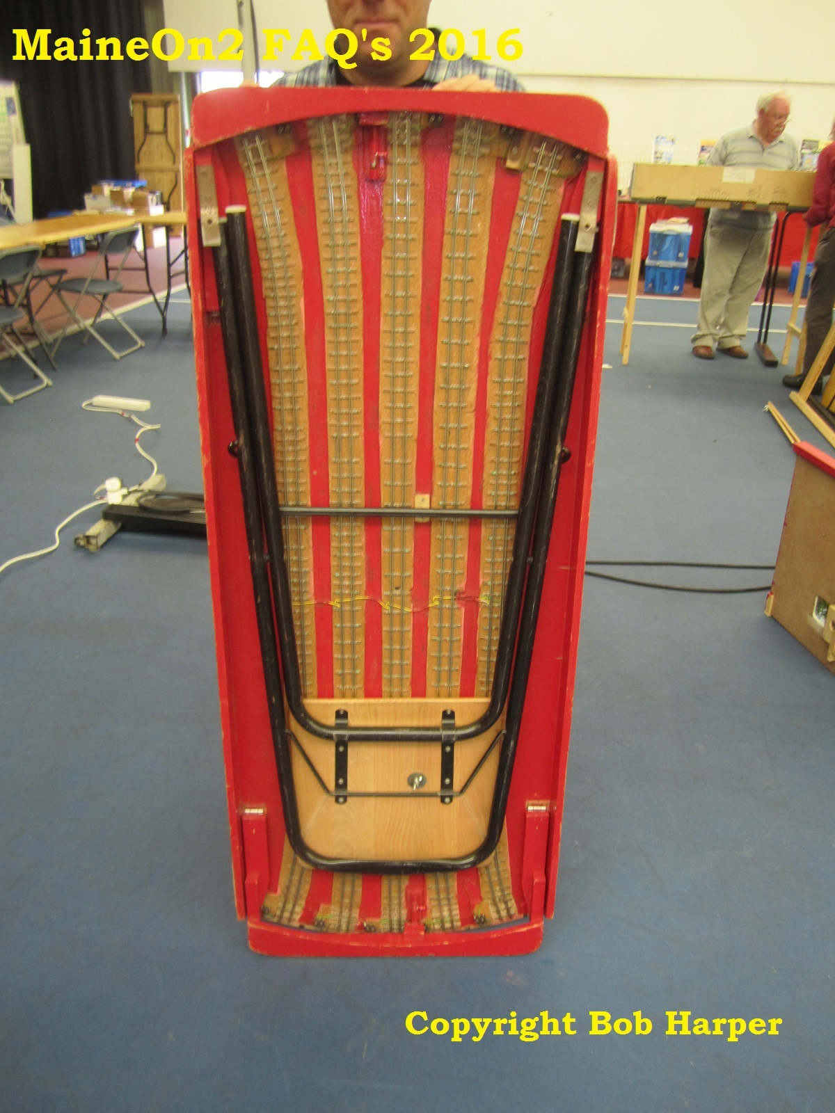
The turntable style fiddle yard as folded for travel.
The legs hinge upwards (in this view) and are locked in place by struts with toggle latches.
The unit is rolled over and upright. This view shows the wooden wheels and upturned furniture castors which assist in taking the weight of the turntable when rotating.
The turntable fiddle yard is fitted with two sets of legs, and so is free standing. Both of the scenic boards are fitted with one pair of legs only and so must be erected and connected to the fiddle yard and first board in sequence. The legs are visible in the heading picture.
The picture also shows the travelling position of an essential piece of equipment, the folding stool which Bob and other operators can sit on at the front of the layout while conversing with visitors and occasionally operating trains.
Bob explains;- “the track on the turntable looks complicated as it was originally built for my On3 exhibition layout, “Cascade Yard”, which has 2 entrances to the yard and is a different width to “Franklin”. When I was getting Franklin ready for its first show I realised that I could share the old fiddle yard with the new layout, by adding the On2 track down the middle of the On3. Hence the 4 rails – 2 gauges, not check rails!”.
After generating some interest on the Maine On2 Yahoo! group, some of it in error, Bob wrote “picking up a few points that have been raised, the micro-switches are needed to isolate the tracks, not flip the polarity. One is needed for each track at BOTH ends of the table. Isolation is required with DC operation, but not essential with DCC. I put the facility in to stop the sound of 5 trains at once driving fellow exhibitors mad at shows, not to stop the locos moving.”
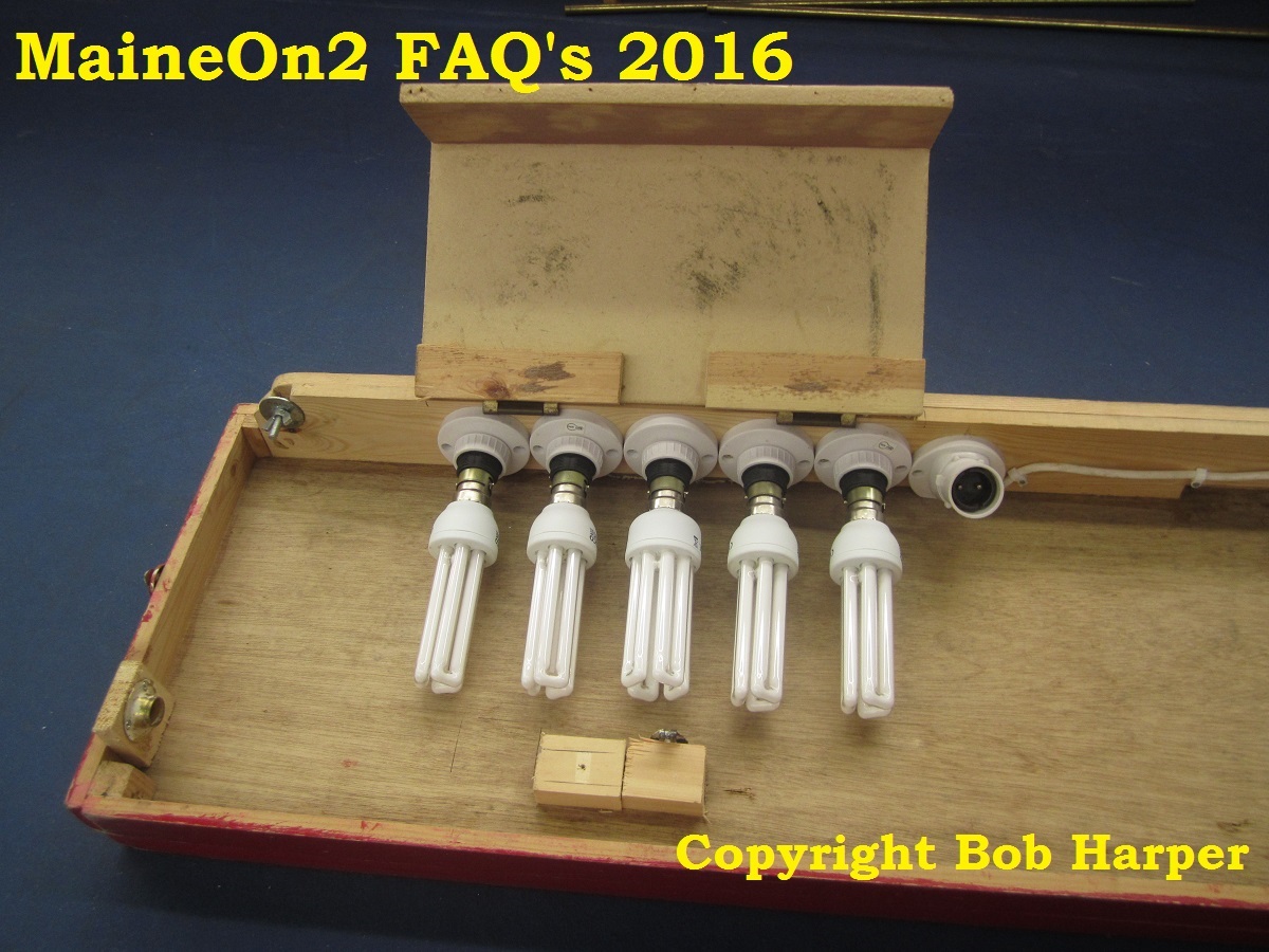
Like many UK exhibition layouts, Franklin has its own lighting system, built into a folding fascia that frames the layout like a theatre proscenium arch. Illumination is provided by a set of CFD “bulbs”, which were rather expensive on initial purchase in the UK when the layout was built.
In transit, these expensive bulbs are housed in dummy bulb holders (ie not wired up) under a protective cover;-
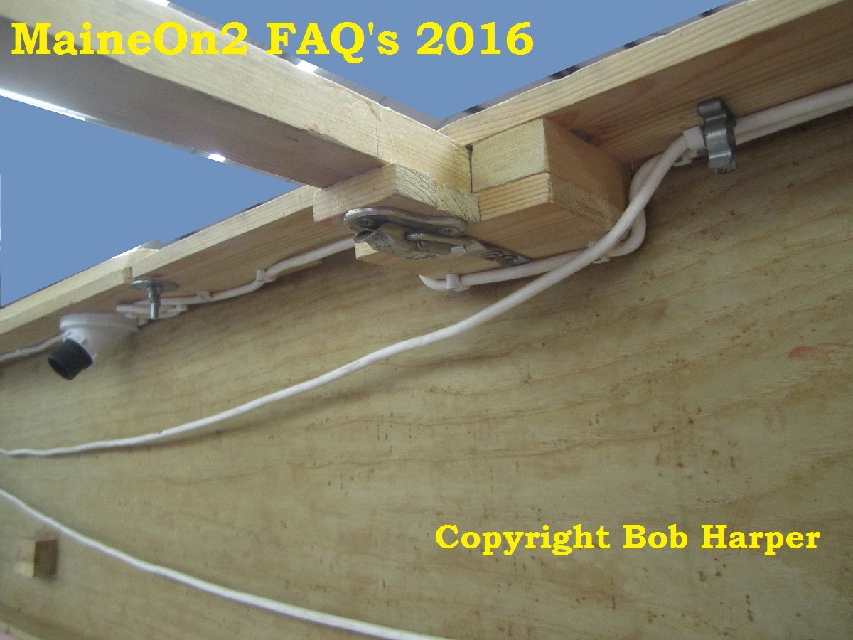
The fascia is supported by cantilevered brackets attached to posts at the rear of the layout, and held in place by toggle latches. Just visible at the top left of the fascia is the locking strip which fits across the top of the hinge line to hold the to parts open and in line;-
The picture below shows the general arrangement of the layout from rear;-
A “before the storm shot” below; the layout has now been fully erected, and after an electrical check can be connected to the mains supply, and rolling stock un-packed, and the paying visitors admitted.
Note the use of a cloth curtain in the picture below to hide all the detritus under the layout visible in the heading picture.
– and here’s the continuation shot showing the turntable fiddle yard ready to accept the rolling stock.
The red end stops are always kept down at the outer end of the table, and at both ends when it is being rotated.
Bob comments;- “As a space saving device, a turntable fiddle yard is very useful to save length, but do remember that you will need more width – you need a square space to allow full rotation of the table. So it can’t be set up close to a wall. However, a friend has got round this by having the whole thing on runners, like a drawer, which pulls out and then allows rotation. Also I now use much niftier castors to support the table, which fit into a recess in the sub-base.”
Footnote 1: Bob and the Franklin module crossed the pond to attend the National Narrow Gauge Convention 2016 in Augusta, Maine in September 2016.
Footnote 2: The Slim Gauge Circle is an informal group of around 200 UK (plus some overseas) based modelers interested in North American narrow gauge railroads. The Circle was founded 30 years ago to provide an alternative meeting place where the emphasis was on modeling, exchange of ideas, meeting old and making new friends plus some trading. Members’ interests include Colorado, Maine, logging and mining in all scales. The Circle holds “get togethers” twice a year at Hillmorton, near Rugby, in May and November.
Click here for more details about the Slim Gauge Circle.
Footnote 3 (update 31-12-2016): In October 2016, Franklin was awarded the David Lloyd Trophy for the “Best Layout in Show” by popular vote at the Expo Narrow Gauge Show held at Swanley, Kent. This is the biggest show in the UK devoted to small scale Narrow Gauge Railway Modeling. Click here for more details about the David Lloyd Trophy and here for more details about the Expo Narrow Gauge Show.
Over the last few years Bob Harper, who hails from Manchester in England, has been doing a great job showing and publicising real Maine On2 on the UK Exhibition circuit with his “Franklin” module.
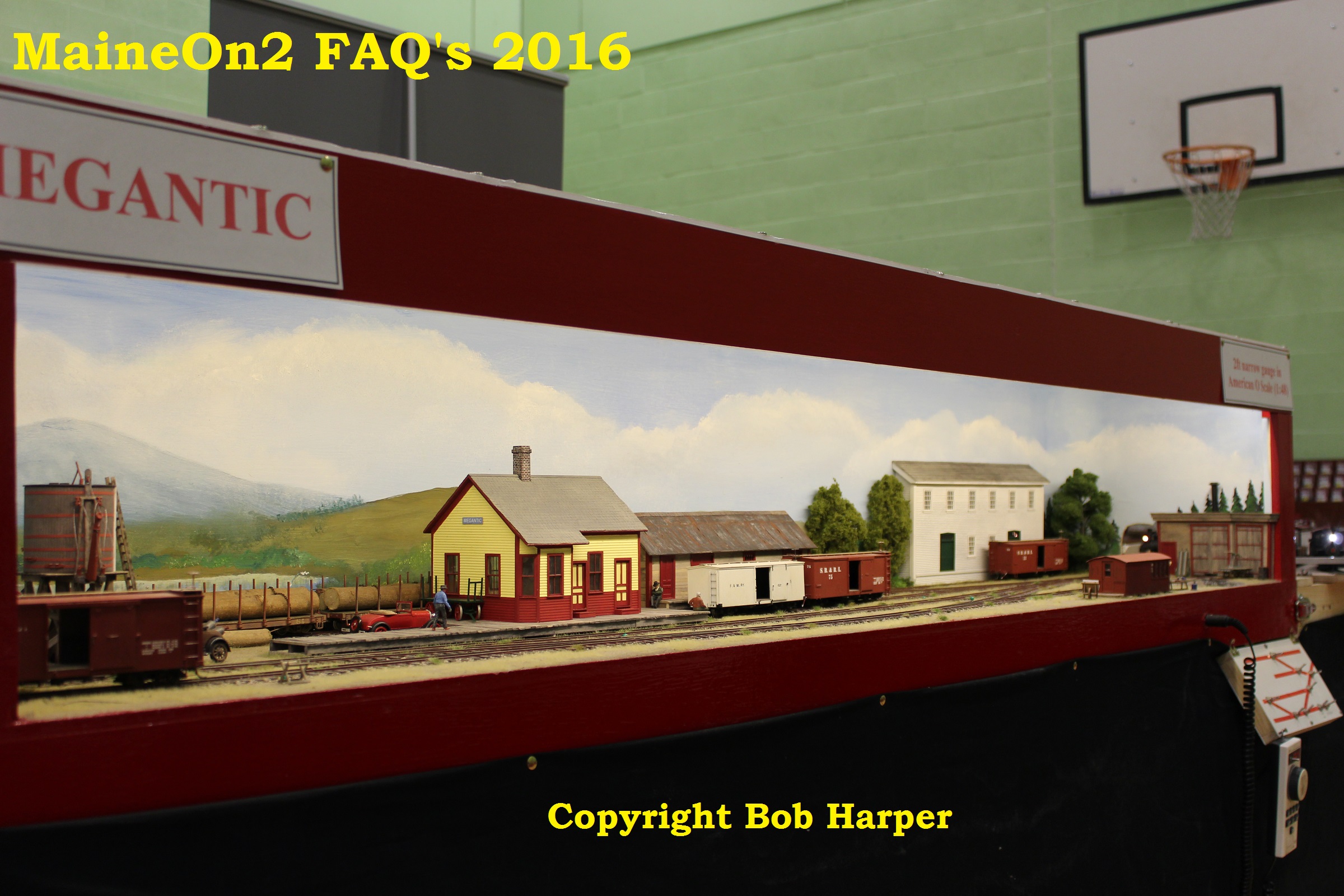
Pictured above is Bob’s new module “Megantic” at its first public outing at the ALSRM (Association of Larger Scale Railway Modellers) North 2016 Show at Wythenshawe yesterday (14th February 2016). The modules are parts of his On3/On2 layout located in the basement of his home which have been designed to be removable for exhibition purposes.
Bob has a very relaxed style of operating at UK Exhibitions, and so the controls are placed at the front to enable Bob to chat easily with the audience. It is not unknown for him to hand the controller to a member of the audience to allow them to run the trains.
Note that all the pictures in this post are shown reduced. By clicking on the pictures the larger versions are shown, use your browser back arrow to return to this page.
Bob sent the first pictures last week and wrote;-
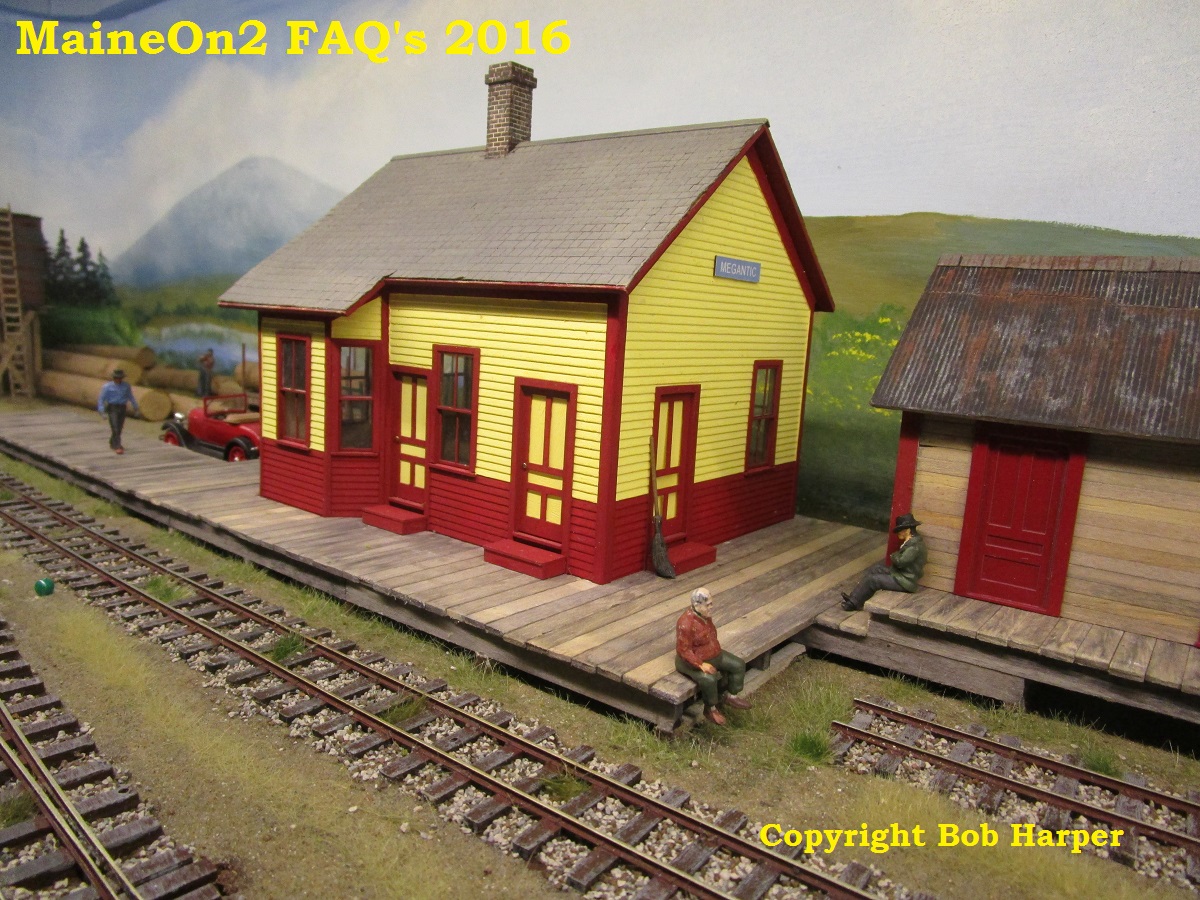
“I’ve been working furiously on the Megantic module trying to get it mostly ready for its first proper outing at the Manchester O gauge show this coming weekend. This will be the last new station on the 2ft, as there is no more space in my basement! It would be nice if it was far bigger, but it’s the best I can do. Very roughly based on Bigelow, the granary and section hut come from Kingfield, station from Mount Blue Models kit and freight house (much reduced) from Bigelow, loco shed from Randoph (reversed), turntable from Bridgton, and factory (chair mill?) inspired by another Mount Blue Models kit. Come and see it and help operating next Sunday if you can get there. Real ale on tap at £2.50 a pint!”
In response to the posted question below Bob has replied;-
“the scenic station section is 80″ long by 15″ deep, and the fiddle yard adds another 40″ to the length. Because of the rotating top, this is effectively 36″ deep, though only 24” when stowed “line ahead”. Everything is very tight, both in length and depth, with the station restricted to Forneys; in order to get in a run-round loop long enough for a 2 car passenger train, l had to reduce the head-shunt by the tank to the bare minimum, and also the turntable, so tender locos won’t fit either. Of course, at home I can use a pilot loco to release the tender locos, but for exhibitions I will stick to the shorter trains and locos. The white background mill is not a Ken Berlo kit, as he has designed his with the freight doors at a pitch to match 2 Bachmann box cars. I scratch-built my version based on Ken’s, but put the doors on 28′ centres instead. I had also run out of window mouldings, so had to reduce their number!”
In December 2016 Bob posted to the Yahoo! group:-
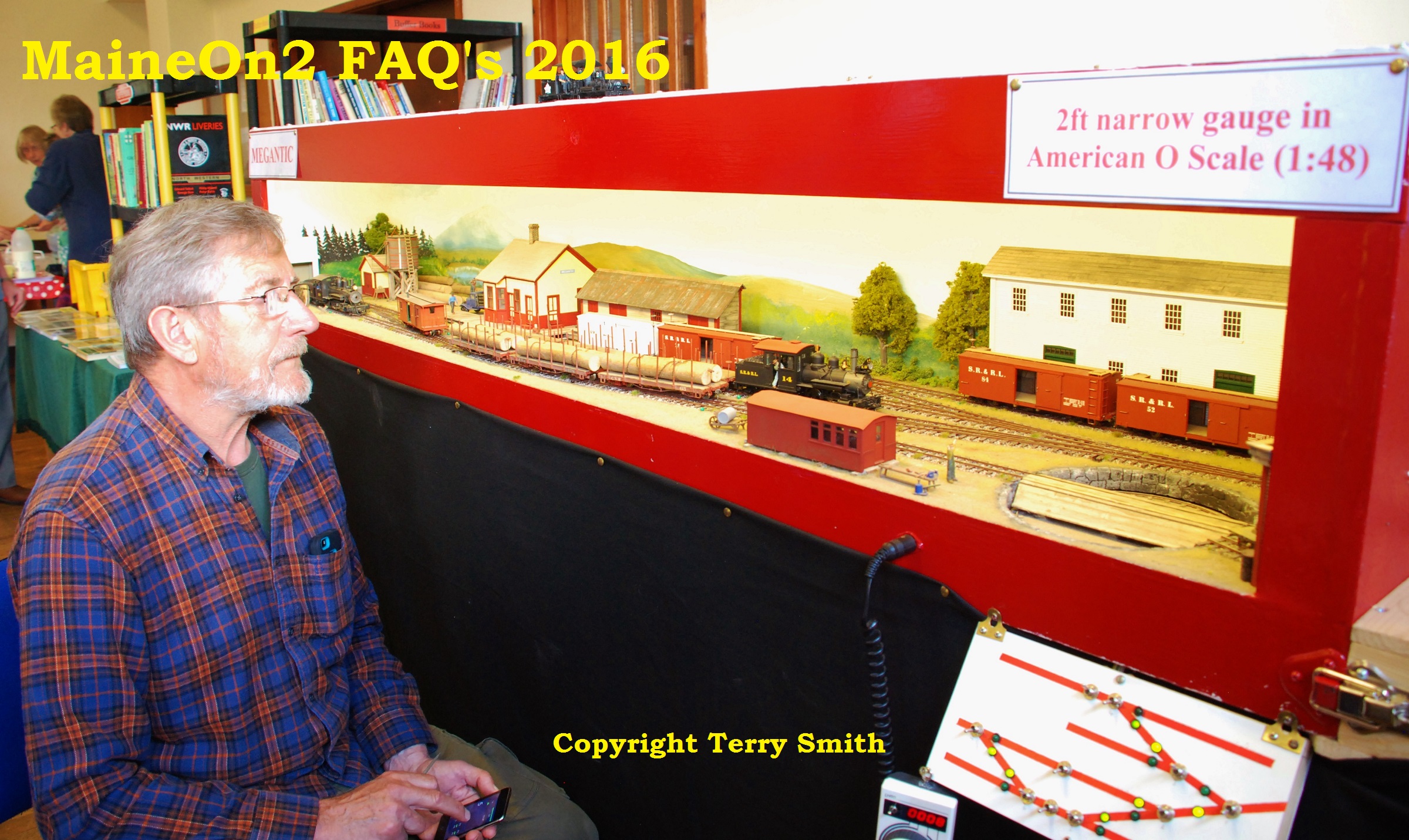
“I decided to use LED lighting on my most recent layout, Megantic. I have used a double strip of Warm White LED’s as close to the front as possible and slightly angled to shine into the scenery. I played around with the height of the strips until I got a good general illumination, but the biggest improvement came when I added a ceiling so as to enclose the whole scene. Have a look at pictures of the layout on MaineOn2 FAQ’s. If you are able to enclose your scene like this, the result is very even and natural, and I’m pleased with it. However, I suspect that LED’s become more and more ineffective as the depth and height of the scene increase. So it’s a matter of trial and error to see what works best. One crucial thing I have discovered is to do all your scenic colouring using the final lighting that you intend to view the layout under. We built one layout forgetting this, and a brownish wall burst out into bright red when we put the exhibition lighting on!”
Bob’s modules are parts of his On3/On2 home layout which are removable for exhibition purposes where they are mated with a turntable style fiddle yard section to hold trains “off scene”. This type of layout is very popular on the UK Exhibition circuit. Bob’s open style makes it easy for the viewers to look over the stock held in reserve, rather than making them strain over view blocks.
The editors made a deliberate decision to publish these pictures at full frame to allow our viewers to see the backgrounds – which are typical of many UK shows.
The section hut comes from the SR&RL at Kingfield.
The station was built from a Mount Blue Models kit of Bigelow Depot.
This structure was scratch-built and represents a prototype industry believed to be a chair factory. The design was based on the Mount Blue Models kit “Backdrop Industry #2”.
The loco shed is based on the Kennebec Central shed at Randoph (reversed) and the turntable is based on the B&SR’s at Bridgton.
The freight house is based on the SR&RL prototype at Bigelow but is much reduced to fit the available space.
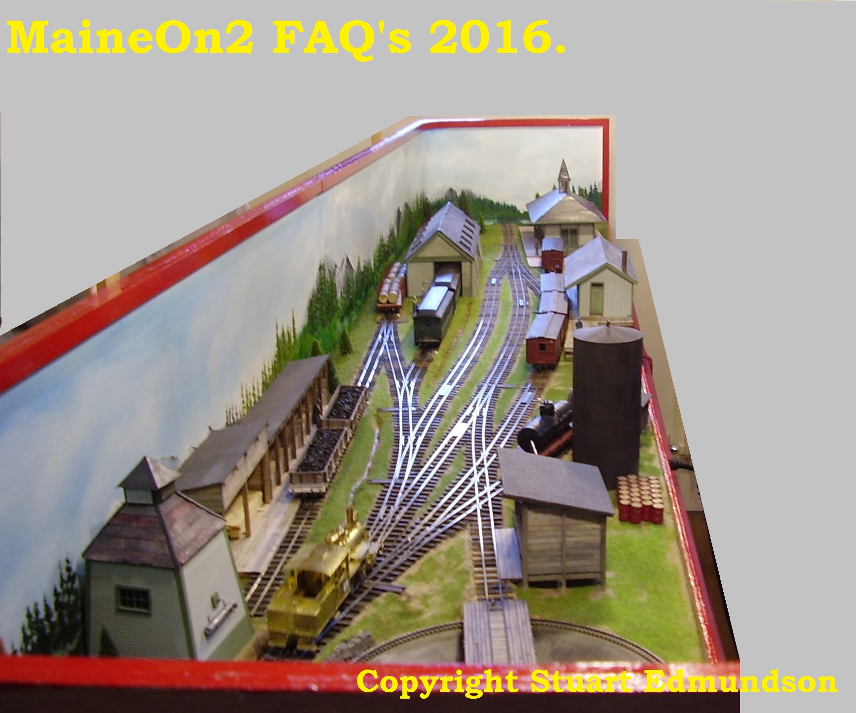
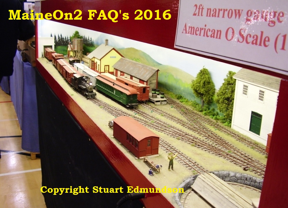
Stuart Edmundson was at the show sent in the following pictures showing trains on the module.
Bob’s latest addition to his fleet of scratch built rolling stock is this caboose based on the early version of the Bridgton lines prototype.
Megantic at the Llandrinio Get Together, Sunday 3rd July 2016
This get together was organised by the UK Borders Model Railway Club for the Gauge O Guild at Llandrinio village hall. Llandrinio is just four miles up the road from Welshpool, which may be familiar to Two Foot Fans.
Bob Harpers’ introduction for the Megantic module.
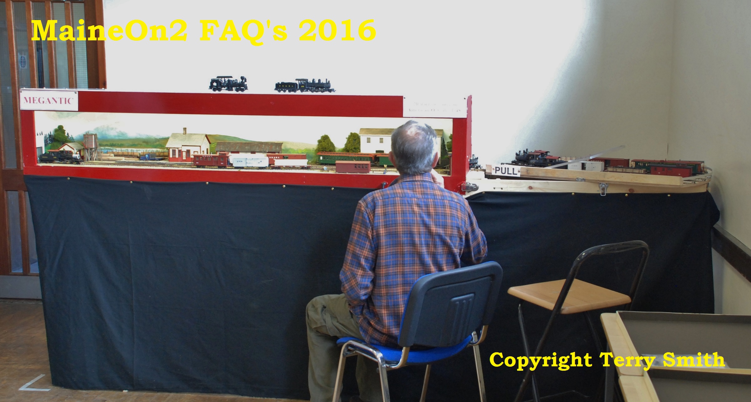
The Megantic module plus turntable fiddle yard plus operator and spare seat set up in the corner of the main hall.
John Pearson concentrating on driving a train through the end board into the fiddle yard section.
Now you can see why John was concentrating! A tight squeeze through the endboard!
Bob Harper adjusting the track between the scenic module and the turntable fiddle yard. Also shows the rolling stock. Note that Bob uses acrylic based paints from “rattle cans” to paint his stock. For the passenger stock he uses Humbrol Brunswick Green, and Halfords Red primer or Red Plastic Primer for freight cars. The 2 reds are slightly different, so give a bit of variety.
Close up of the front mounted point control board and a tethered throttle . The Megantic module uses servos as point motors.
The mobile phone used as a throttle. The speed CV is correctly shown as 77, inadvertently set by the handling of the phone for this picture. It was very rapidly reset to slow the train down immediately afterwards.
Bob’s ipod railway controllers use an APP called Touchcab and communicate with the Lenz DCC system via WIFI / radio waves.
This low angle shot catches the nicely done clouds on the backdrop.
The host club has now posted a report of the day. Click here to view on another page.
Some notes from Bob Harper on point tie-bars and reliability.
This photo shows part of my On2 yard, where I use hand-throws, which also throw a microswitch, hidden under the scenery, to change the polarity of the live frog.
Most of the points on my Franklin and Megantic modules are actuated by Tortoise switch motors. The slow movement is only part of the reliable operation that I seek to achieve. Ever since I started building my own track 40 years ago, I have completely avoided soldering the point blades to the copper-clad tie-bars. The endless flexing of the soldered joint will inevitably lead to the joint snapping eventually, (and sooner rather than later if you use solenoid type point motors), and the most used (and hence most important) points will go first – usually at about lunchtime on the Saturday of a 2 day exhibition. I’m sure you can remember seeing a large exhibition layout at a halt as somebody tries to solder the crucial points up again.
My tie-bars are still copper-clad for strength, but upside down, with a 0.8mm hole drilled through at the position of each rail. A short length of brass wire in the shape of a Z is pushed through each hole and soldered to the side of the point-blades but obviously not soldered underneath to the copper surface. I used to use dressmakers pins pushed up from underneath and then bent over and soldered to form the pivots, but all the ones I can get now seem to be far too brittle and snap when I try and bend them.
Electrically it as all very simple – what I would call “best-practice” DC – though in fact I operate the whole of my 2ft and 3ft empire, including the Franklin and Megantic modules using DCC. This means having live switched frogs, which is easily done using one of the changeover switches on the point motors or using an extra set of poles on the toggle switches that throw the point motors which is my preferred method. I have found that separate electrical feeds to every length of rail, no matter how short they may be, are essential. I do have isolating sections on the loco shed roads, and more could easily be added for a DC layout, but I use them to cut down on the noise from stabled locos that are DCC sound fitted.
This photo shows part of my On3 yard before I painted and ballasted it, so the tie-bars can be seen better. I have used all copper-clad ties for quick, soldered, construction, but on more visible sections, I would mostly use spiked, wood ties apart from a few copper-clad ones to give strength at the switch throw and frog. The copper-clad comes in paxolin-backed (poor) and glass-fibre (good!); looking carefully you can see the lighter green mark across parts of the tie bar – this is where I have cut insulating gaps underneath. Depending on where I can fit the Tortoise underneath dictates where the gaps go – I try to leave the area underneath where the pivot pin comes through completely isolated, just in case!
This photo shows what the copper-clad ties look like when painted and ballasted.
And here’s a picture of the same area of real Maine Two Foot point taken earlier this year.
Note that Bob’s Franklin module has featured in a number of publications such as the UK 7mm Association newsletters and the Narrow Gauge & Shortline Gazette, September/October 2014 edition, and attended the US National Narrow Gauge Convention in Augusta, Maine in September 2016.


You must be logged in to post a comment.