Tin roofs and colour schemes, edit date: 04-06-2015 Grantham 1, updated 13-11-2015.

Key Points
As this is a long post, we present some of the key points that will be expanded further in the post;-
With only a few exceptions, all Maine Two Foot equipment; freight, passenger, and locomotives were roofed with tin sheeting. There is a misconception that canvas or tarpaper was used. Jeff Bissonnette
The exceptions are the rail autos/buses. G Kohler HOn30 response
Don’t run for the hills… the point is that the vast majority of Maine two-foot equipment had tin roofs. Some have tried to argue/”speculate”/justify whatever… that equipment had “tarpaper” or some other treatment. The bottom line is that all of the surviving equipment (that wasn’t Edavillized or covered with asphalt roofing material at Phillips) still have their original tin roofs. This is a testament to both the longevity of the material and the reason why it was chosen over other roofing materials in the first place. Chris McChesney
Standard practice was to coat the tin seamed roof with a preparation referred to as “red lead”, and this preparation was most likely mixed up on site from a paint base (boiled linseed oil?), binders and pigment (the red lead itself). Red lead is the common name for the mixed oxide of lead (Pb3O4) which in its pure state is a bright almost virulent orange colour. When mixed as a paint locally, various correspondents have indicated that colour can appear as anything from orange through to brown, and it has been described as “fugitive” ie rapidly changing. Wes Ewell, Bob Schlechter & others.
Red Lead is similar to the SR&RL “Freight Car Red” but is absolutely flat. This red is not like Floquil’s “Boxcar Red”. I use Floquil’s “Oxide Red” for roofs, sometimes cut with white for older cars. Chris McChesney
SR&RL “Freight Car Red” – This red is not like Floquil’s “Boxcar Red”, which is way too brown and is a match for D&RGW’s boxcar red. Chris McChesney
The closest out of the bottle color I have found is ATSF Mineral Brown. G Kohler 12/12/12 MaineOn2
15-12-2016: Check out David Keith’s posting “Search for SR&RL freight car red” using currently available (in the USA) paints. Click here to view on another page.
By the end of operations, the tin roofs on Maine two-foot freight cars were a dark brown rust color because… their red lead paint jobs were not maintained and the tin rusted! Chris McChesney
Roof walk boards were normally left unpainted. Painted wood and rain lead to slippery conditions. Wet, raw wood weathered with raised grain is much safer for a brakeman to walk on… especially when a train is in motion. Chris McChesney.
List of Contents
The tin roof: its use on prototype rail vehicles, structures and the tin materials.
Modelling tin roofs, a selection of modellers methods from the Yahoo! groups.
Prototype “red lead” and Maine Two Foot “boxcar red”.
What is red lead?
Modeling Red Lead
Boxcar color- Freight cars and models
Commercial paints available in the Maine Two Foot era
Prototype Paint Schemes, selection by road name and vehicle type presented on the Yahoo! groups.
The tin roof; its use on the prototype rail vehicles, structures and the tin materials.
The tin roof; its use on the prototype rail vehicles.
With only a few exceptions, all Maine Two Foot equipment; freight, passenger, and locomotives were roofed with tin sheeting. There is a misconception that canvas or tarpaper was used. Jeff Bissonnette
The exceptions are the rail autos/buses. G Kohler HOn30 response
Don’t run for the hills… the vast majority of Maine two-foot equipment had tin roofs. Some have tried to argue/”speculate”/justify whatever… that equipment had “tarpaper” or some other treatment. The bottom line is that all of the surviving equipment (that wasn’t Edavillized or covered with asphalt roofing material at Phillips) still have their original tin roofs. This is a testament to both the longevity of the material and the reason why it was chosen over other roofing materials in the first place. Chris McChesney
The pieces have a lip on one side and the top. They are nailed at the edges. The next piece is applied over the nails and then the lip of the first piece is bent over the seam, covering the nails. Finally a bead of solder is run into the seam. The porch roofs on my 1932 house are done the same way and the seams are still as tight as the seams in a tin can. Jim Pasquill.
The tin roof; its use on structures
The metal panels were probably not pure tin, but “terne” plate which is tin-plated steel. When the tin plating wore off, the underlying steel would rust. See recent photos of the Strong creamery for a good example of this phenomenon. Note that the roof on that building is 97 years old and has been painted a few times. Wesley Ewell, December 2012.
Tin roofs hold up better on a building than on a car. The car begins to flex during movement as it loosens with age. This cracks the solder seals. The result is bad roof leaks — a problem we are fighting currently at the wide-gauge East Broad Top. Lee Rainey
The tin roof; the tin materials
There are three possible candidates for the tin sheet material in a historical context, tin coated steel, zinc coated steel and terne plate. Terne plate was sheet steel coated with a lead/tin mix. Modern research has shown that the lead/tin ratio varied widely, and that contemporary accounts at the time of initial building of the Maine Two Footers and their rolling stock did not distinguish between tin coated steel, zinc coated steel and terne plate. Terry Smith, December 2012.
Based on a report from Gary Kohler that the underside of a piece of boxcar roof in his collection “is as bright as the day it was made” suggests that it was made from what we would now classify as tin coated steel, as both zinc coated steel and terne plate would go dull as they aged. Terry Smith, December 2012.
Bob Troup has mentioned 30 and 32 gauge in a posting he made about tin roofs that he has seen while refurbishing cars at the SR&RL Museum. Depending upon the material and the exact gauge scale referred to (unspecified in the posts) the actual thickness of the tin sheet material could range from around .008 inches to around .013 inches. These seem low/thin to me, but an actual measurement would be valuable. Terry Smith, December 2012.
Roof walk boards were normally left unpainted. Painted wood and rain lead to slippery conditions. Wet, raw wood weathered with raised grain is much safer for a brakeman to walk on… especially when a train is in motion. Chris McChesney. However, a later posting suggests that some roof walk boards were painted – and this has been observed in some museum restorations.
Tin sheet comments from Bob Troup:
The common tin size was 14″ x 20″ with 5/16″ seams bent over, interlocked with the adjoining sheets, and soldered (flat seam soldered). As each sheet was applied it was either tacked through the seam (Laconia), or a tin strip typically 3 inches long and perhaps 1/2 inch wide hooked into the seam which was in turn tacked to the roof (Portland Co.). Roof edges were tacked to the trim or weather board every inch. On passenger cars this is not visible because a drip strip was soldered over these tacks (actually formed to a mini gutter over the platforms). Yes, all tin roofs were on a steel substrate, 30 gauge – perhaps 32. Forming compound curves on passenger car corners is a bear particularly if the steel has too much temper. You can roll the sheets to form a compound curve, then at the very corners bend a “hospital corner” just as you would on a bed sheet and hammer it until it lays down the way you want it – tack in place and solder to hide.
But, SRRL Box 155 had a mix of 14×20 and 20×28 sheets with a manufacturer’s stamp that dates to its original build date. Portland Co. ran out of one size of tin perhaps???
Laconia coaches were, and are, definitely tin. The Lower portion of roof is 14 x 20 5/8 sheets while top of clerestory is the conventional 14×20.
Historically, tin roofing was sold by the basebox = 112 sheets of 14×20 tin. For roofing tin, the plating was 4 – 5 lbs per basebox. They still talk about the plating in terms of lbs/basebox even though it is only sold on rolls now. Now it is all electroplated to about 0.25 lb/basebox which is not even close to adequate for roofing. The original process was a dipped plating and the practical dip tank held a 14×20 sheet. Galvanized material took over for roofing, but is not solderable once the zinc oxide layer forms.
All of the tin comments are based on my experiences re-roofing boxcar 155 (completed) and SRRR Coach 5 (in process), including careful measurements before I started.
Bob Troup, Secretary, SR&RL RR Museum, 2006.
SR&RL Boxcar #155 Tin roof – original and replacement at the SR&RL Museum
The following set of pictures and plans are published here courtesy of Bob Troop and Els Gray, and show the original tin roof of SR&RL boxcar #155, and its replacement at the SR&RL Museum in 2006.

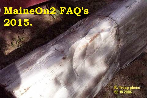
The underside of the original roof covering. Note the bright appearance (contrast to the exposed surface) and the tacks/nails protruding from the seams.


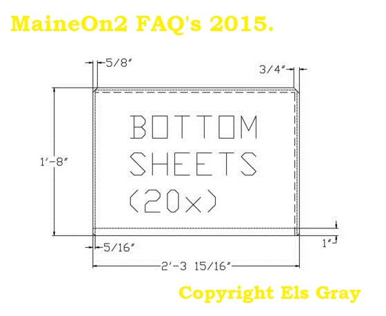
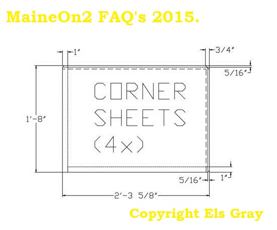
Els Gray produced these sketches from dimensions taken by Bob Troup as an aid to modellers.

B&SR;- My own observations (Bridgton boxcars) are that the “central” or longitudinal seam appears to be much more obvious than the crossways seams. I don’t know if this is because of different seam constructions or simply a trick of the light. Panels appear to be square, and sized 18″ x 18″. Terry Smith, February 2005.
WW&FR Boxcar Tin roofs
An off-board discussion has led me to look into the question of how boxcar tin roofs were laid, and what the pattern of seams seen should be. The revised edition of Jones and Register’s “Two Feet to Tidewater” shows a picture on page 217 of the Whitefield wreck, taken from the top of boxcar 509. The picture in the revised edition is not as clear as that shown in original copy, but shows two longitudinal seams on one roof panel (ie half the total car width) and it appears that the transverse seams are quite close together on either side of the longitudinal seams, (ie not staggered by half the panel length as is suggested by the B&SR practise). On page 368 there is a bill of materials for an order of 10 boxcars, which turn out to be the 30 foot boxcars numbered in the series 65 to 74 built by the Portland Company in 1906. The bill shows “Tin to cover 2200 sq ft of roofing. 133 sheets to one car. 112 sheets in box” Order shows 12 boxes Tin 14″ x 20″.” Doing some figuring equating the area of each sheet with the total area specified shows that the seams used 5/8″ material from each of the four sides of the piece of tin, making the laid panel clear size 12 ¾ ” x 18 ¾” separated by 5/8″ seams if single lapped. The evidence from the picture of the Whitefield wreck suggests that this car (if it used the same size tin sheet) had the sheets laid with the long dimension of the sheet laid lengthways along the car, and that the transverse seams were only a couple of inches out of line across the car. In contrast, a picture of car 502 on its side on page 45 of Kohler and McChesney “Narrow Gauge in the Sheepscot Valley” volume IV appears to show only one longitudinal seam along the lower roof half, and the individual panels appear narrower along the length of the car compared to the width (making due allowances for the relative angles), and the transverse seams appear to staggered by half a width in the two rows. This pattern could occur if the sheets are laid with the long dimension of the sheet across the car roof with the shorter dimension along the car roof. The half panel staggering is also seen in the lower picture on page 48 of the same book. Some of the pictures could be interpreted differently, and often the detail is lost in highlights etc. If anybody has other (and better) pictures and/or alternative interpretations then please post a reply. Looks like any Wiscasset modeller who wants to model tin roofs is going to have fun! Terry Smith, January, 2007.
Prototype Wiscasset tin roof panel
The following set of photographs come from Marcel Levesque and show a section of tin roofing salvaged from a farmer’s field near the Albion Station site. Marcel writes “Stories say that two cars were brought to the field and attached together to make a livestock shed. This section of roof material was salvaged about 10ish years ago. It either comes from box #82 or flanger #202 which were both on site from the inventory of rolling stock taken. It will probably answer some questions and most likely raise more……..”.
These photographs are noteworthy for showing clearly the details of the seams, the angled folded corners to each “square”, the tacks which hold the tin square down and the laying pattern of offsetting the transverse seams by half a width in the next row.

View of the underside.

View of the underside. Note the tacks used to attach the tin to the roof.

View of the underside.

View of the underside. Note the tacks used to attach the tin to the roof and the angled folded corner.

View of the exposed top surface of the original roof.

View of the exposed top surface of the original roof. Note how flat the seams appear.

View of the folded seam from the top, note the tack head not quite covered by the fold.
Modelling tin roofs, a selection of modellers methods presented on the Yahoo! groups.
Gary Kohler wrote: There is an excellent article by Mark Hall on “Building Metal (Tin) Boxcar Roofs” in M2FQ Vol 3-1, 1997, and another by Gary Kohler on rusted tin roofs in M2FQ Vol 47 1995.
Jeff Bissonnette wrote:Gary Kohler came up with a good way to do this, and I modified it some to make it a little more convenient (IMO) for modelling. Gary suggested Mylar, but I switched to Evergreen 0.005″ thick styrene sheet. What to do is simple. I laid out the 18″ and 27″ divisions on the styrene using a soft pencil. Then place the sheet of styrene over a sheet of basswood. Using some sort of ball ended scriber (ball point pen, or a rounded off scriber), “draw” the panels into the styrene using light pressure. The basswood sheet underneath supports the material, but still allows the scriber to force a fine line into the styrene. The last step is to heavily scribe the roof peak into the sheet so that the “tin roof” can be bent to match the pitch of the car roof. Use ACC or epoxy to glue to the car roof, and once dry, trim off the excess. This technique works well for HOn2/n30, but looks especially good for Sn2 cars. If you’re not crazy about using styrene, craft stores carry small rolls of 0.002″ thick copper sheets that would work just as well, maybe better. The problem with aluminium foil is that it is so thin and is easily torn or distorted. Another method is to scribe the panel pattern onto an existing resin or styrene car roof, then apply aluminium tape (used for duct work) over the entire surface. Burnish with a soft stick or “Q”-tip and it gives a really nice effect. You can even carefully trim the material so it can be bent over the edges, just like the prototype cars. A recent communication from a museum (think it was Sandy River) had a report that the superintendent had ordered tin sheets 18″ x 27″ to re-roof something. M2FM had an article years ago that said that they were roughly 18″ x 27″ panels. Though some Maine Two-Foot cars had smaller panels as well. It depends on the car and even the era modelled for any one car.
In 2006, there was a flurry of postings on the Maine On2 Yahoo! group which reported what various modellers were doing or suggestions to use for representing metal seamed roofs;-
Bill Kerr: I do not use foil. I build in styrene, so I use .010” x .020” styrene strips to simulate the seams. After gluing down, I sand the strips down to almost nothing.
Elliott Thomas suggested: Try the silver tape used in ductwork (not duct tape!) It is thin, and goes on easily. It will take paint and is available at many larger hardware stores.
Doug Rowe added: I have read that some folks use the aluminium tape that air conditioning & furnace repairmen use to seal ducts- not “Duct Tape.” This stuff is like aluminium foil with a sticky back, and comes in rolls.
Keith Gutshall: I use the foil disposable cookware from the supermarket. The foil is thicker than the rolls and tools very good. The cookie sheet yields the most flat stuff to work with. Goo or a similar contact glue would work best, because a flexible glue seems to work best with the metal and the wood.
Terry Smith: I use two methods, either a styrene roof panel and then add chart tape for seams, and use paint applied by brush to soften the hard edge and as extra “glue” or I have used the same panel as a master, adding the roof walk supports, and then casting urethane complete roof sections using an RTV silicone rubber mould. I have heard of using paint or varnish as a fixative for metal foils in plastic kit building.
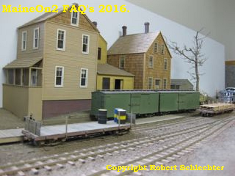
The picture below shows the taped seam roof on the right (and historically incorrect representation of tarpaper roofs central and left).

In June 2007 Trevor Marshall wrote about using “embossing foils”, which he then cut into individual pieces and glued to the sub-roof to produce overlapping seams, shown below.

Shortly afterwards Terry Smith used the same materials, (ArtEmboss by Amaco, in particular #50068T; light aluminium) to produce an embossed half roof panel which he then copied in urethane resin using RTV Silicone Rubber moulds for his own 26 foot B&SR boxcars. The two pictures below show one of these roofs under directional lighting (both from the right) in order to show how the lighting emphasises the seams along and across the roof differently.


In 2010/2012 John Rogers wrote: I use stained glass copper foil with an adhesive backing in the 3/8” width size, cut to length. It works great. Apply it to wood that has been sealed with two coats of clear brushing lacquer and it will adhere very well. After it is on, I put a coat of brushing lacquer over the copper to help keep it from peeling up at the edges. A picture showing this technique on a caboose roof is shown below.

In early 2013 Terry Smith posted a summary of his foil roof experience to the Maine On2 group after a number of offboard questions;-
When I first started out on my Maine On2 modelling journey around 1990, I tried using domestic aluminium cooking foil to represent metal roofs, as suggested by Peter Barney in his SRCS kits, but I could not get it to work for me. I found it way too fragile and too prone to unintended embossings and it also shows glue thickness variations. Standard UK domestic aluminium cooking foil is only 0.015mm/.0006” thick, which is too thin for this type of application. That’s when I started to use a replacement styrene roof panel plus self adhesive chart tape to represent the seams. The tape is Letraline by Letraset and the writing on the cassette is 3005 .5mm black flex 3112. I bought mine 20+ years ago and I’m not sure if it’s still made or available.
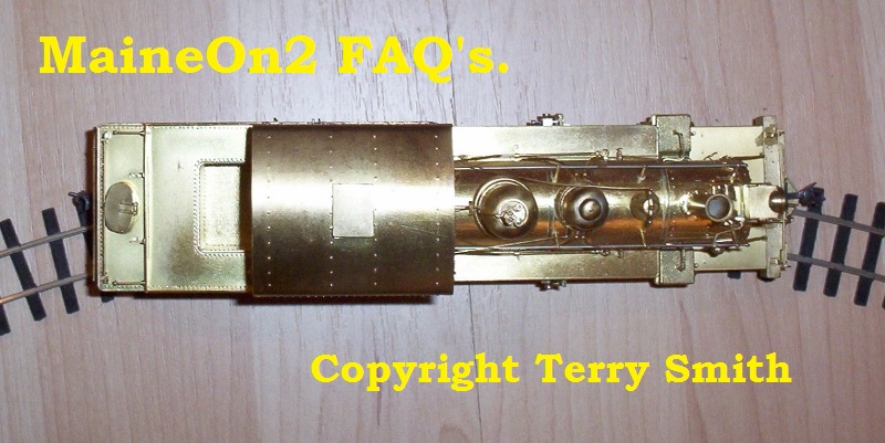
Then sometime after I joined this group (Maine On2 Yahoo! group), way back in the 2002/03 period, Bill Kerr published a picture of a SR&RL metal roof from Jeff Bissonette (the heading photo of this posting) which opened my eyes to just how subtle the seams needed to be, and then sometime around the 2006/07 timeframe, Trevor Marshall mentioned the Amaco ArtEmboss materials.
I have trialled a number of the Amaco metals and thicknesses;-
50063M; medium pewter, 0.17mm/.007” thick, weighs 122 grams per 9¼” x 12” sheet.
50067S; medium aluminium, 0.17mm/.007” thick, weighs 26 grams per 9¼” x 12” sheet.
50068T; light aluminium, 0.09mm/.0035” thick, estimated weight 13 grams per 9¼” x 12” sheet.
Pewter is really nice for its finish and ease of embossing, but I found it rather heavy and floppy to use for a single/one half roof panel. It’s great as a replacement for the soft metal foil that I used to get from Drambuie bottle tops which I used in the past for representing lead roof flashings on roofs.
Although I really like the way the pewter foil embosses and takes impressions, I find the easiest material to work with is the thin aluminium sheet. This is lighter and stiffer and so I can work with pieces that are one piece for boxcar roofs.
I also find it simpler to make a master of the embossed foil (glue it down to a piece of styrene) in order to make a mould because then the resultant urethane part has permanent ridges which are pretty obviously immune to handling damage in a way that the embossed foil itself is not (and of course further copies can be made easily).
The picture below shows the urethane roof that Terry has recently made for a Wiscasset 65-74 series boxcar, with the long edge of the tin “squares” across the roof.

My piece of the thicker aluminium foil (Amaco medium) is pretty much intact, nearly a full sheet, so obviously I have not used it much. I think that I found it too thick for my embossing style and procedures, in comparison to the light aluminium, and perhaps too stiff as a sheet to ensure that it laid flat over a styrene sheet as a master pattern.
The Amaco aluminium foils have a matt, almost brushed surface finish both sides. The pewter has an almost polished finished, but it is not a mirror finish.
I also bought some copper foil/shim 0.09mm/.0035” thick from a different source and found that it was also a usable material for embossing, impressions and handling but was much more difficult to trim, especially at the edges, with a modelling knife and therefore lost out to light aluminium and pewter. It was also more difficult to remove mistakes and unintended embossings from this material than light aluminium and pewter.
None of the metal foils have shown glue lines when using a medium thickness ACC (Green label, Zap-a-Gap Medium CA+ by Pacer) to glue them down over styrene.
Prototype “red lead” and Maine Two Foot “boxcar red”.
What is red lead?
A number of correspondents (including Wes Ewell and Robert Schlechter) have confirmed that standard practice was to coat the tin seamed roof with a preparation referred to as “red lead”, and indicated that this preparation was more than likely to have been mixed up on site from a paint base (boiled linseed oil?), binders and pigment (the red lead itself). Red lead is the common name for the mixed oxide of lead (Pb3O4)which in its pure state is a bright almost virulent orange colour. When mixed as a paint locally, the correspondents have indicated that colour can appear as anything from orange through to brown, and it has been described as “fugitive” ie rapidly changing.
By the end of operations, the tin roofs on Maine two-foot freight cars were a dark brown rust color because… their red paint jobs were not maintained and the tin rusted! This is abundantly evident in the Bridgton & Harrison DVD available from Gary Kohler. There are a couple of shots taken from the roofs of boxcars that will provide perfect color tone and weathering information. Chris McChesney
Question – what color for red lead?
Answer 1: I am a scenic painter in the theater and majored in historic paint formulas of the early period of electric light. Red lead is a color that is all over the board. It ranges from flame oranges to brown. The color was made by a couple of different methods each resulting in a vast array of hues. Add to this variation that red lead (also known as minium) was harshly affected by acrid coal smoke it is almost impossible to speculate on a correct red. UV rays seriously affected the color as it aged and a painted piece could have many variations of the same pot color. Add again the fact that lead and tin may have been mismatched as finish coat and substrate a wide variety of colors could appear.
What am I really saying? Red lead was not a set formula but a purpose made color which changed from pot to pot and from day to day in use. Variations in modeling will present the railroad in everyday use. Unless we all agree to model a specific moment in time we can all have red roofs that are “correct”.
If some one has a sample, a very close color match could be calculated and we could discuss it using a Munsell number, giving us all access to viewing a matched sample then choosing our own shade of red. Brian Goodman
Answer 2: As far as “What is true “Red Lead?” that’s like asking to correctly identify/match “Barn red”. The best you can do is compare what few color photos we have to black and white images and try to draw some logical conclusions. Gary Kohler and I have been collecting samples and analyzing Maine 2-foot colors (and trying to match them in our models) for years. If you really want to see and judge colors for yourself, buy one of Gary’s color CD’s. My favorite is the “Bridgton & Harrison Ry. Video and Photos from 1939-1941.” In a previous post someone erroneously used the word “colorized” to describe the images. Make no mistake, the color in this DVD not colorized like a painted postcard. The color is from real color slides taken by a railfan in the early ’40s. Gary purchased the original slides from a friend of the deceased photographer. The B&H slides are the best color Maine two-foot images we have ever seen. Period. There is no “shifting” or contrast that occurs with copy slides. These aren’t copy slides and Gary hasn’t run them through Photoshop or anything goofy like that (the naysayers need to give it a rest). So, If you want to see the wide range of reds you described (and excellent examples of weathering)… heck if you want to see the best real 2-foot color period, get a copy. No one will have to speculate about UV, coal acridity, chemical reactions with the tin substrate etc. etc. anymore. Chris McChesney
Answer 3: If you review your Sandy River & Rangeley Lakes RR Museum newsletters you will find a series of articles about the stripping of the Sandy River/SR&RL Laconia passenger car in preparation for restoration. In the article, it states that the ORIGINAL color of the paint applied to the TIN roof of the coach was found! It survived because it was in a protected location. The article states that this color is best matched to “Red Lead”. Red Lead is similar to the SR&RL “Freight Car Red” but is absolutely flat. This red is not like Floquil’s “Boxcar Red”. Floquil’s boxcar red is way too brown and is a match for D&RGW’s boxcar red. I use Floquil’s “Oxide Red” (sometimes cut with white for older cars) for roofs. Also in the Sandy River Railroad Museum article, they found an area of the coach that had ORIGINAL green paint on it. The area is the wood found directly behind the brass bell cord sleeves found at the end of the cars above the doors. This color was the color applied at the Laconia car works. The brass bell cord sleeve was applied later. The article states that the original color is indeed best matched to Floquil’s “Brunswick Green”. Chris McChesney
Answer 4: Two-foot coaches, in general, were maintained better and the Red Lead is visible in many SR&RL and B&H coach shots even immediately after abandonment (including the earliest Kodachrome postcards series of the Edaville fleet). If you own one of these postcards of the Rangeley, you will notice that the car sides have been restored and repainted but the Red Lead on the tin roof was left alone. There are dents and areas of bare metal seen in many places on this ORIGINAL roof. Later, this roof was painted by Edaville in I believe black. Chris McChesney
Modeling Red Lead
Red Lead is similar to the SR&RL “Freight Car Red” but is absolutely flat. I use Floquil’s “Oxide Red” (sometimes cut with white for older cars) for roofs. Chris McChesney
I use oxide red with some caboose red mixed in. The red lead that I used to paint my rowboats with when I was a kid was more of a Chinese red, but varied a lot depending upon how thoroughly you stirred it. Wes Ewell
Boxcar color- Freight cars and models
The SR&RL requisition sheets state, “Freight Car Red”. Nothing is more accurate than the real thing and since I’ve found a good piece of existing paint, un-weathered, I have been able to come up with a formula that I feel, as well as others who have seen it, is 98% accurate.
You will need the following paints: Floquil Polly S Metal Primer, Floquil Polly S Roof Red and Model Masters (Acrylic Enamel) Desert Sand. The formula is as follows: Three parts Metal Primer, two parts Roof Red and a touch of Desert Sand. This will get you an almost perfect colour match. For a slightly weathered colour, add a touch of Model Masters Flat White.
SR&RL freight cars were lettered with White Lead. excerpt from Brian Carters page information provided by Gary Kohler, take link for more details.
The SR&RL “Freight Car Red” color is similar to Red Lead, and not like Floquil’s “Boxcar Red”. Floquil’s boxcar red is matched to D&RGW’s boxcar red and is way too brown for a Maine Two Foot freight car – edited from Chris McChesney
The closest out of the bottle color I have found is ATSF Mineral Brown. G Kohler 12/12/12 MaineOn2
15-12-2016: Check out David Keith’s posting “Search for SR&RL freight car red” using currently available (in the USA) paints. Click here to view on another page.
Commercial paints available in the Maine Two Foot era
Bob Schlechter has sent some useful background information: most paint colors prior to 1940’s were not available ready mixed off the shelf as they are today. My grandfather and father were painters by profession and they had to make up colors by adding tinting colors from a tube of concentrate color. It was a very difficult task to match colors exactly unless one was a very good professional. This accounts for the many variations that resulted.
White lead, linseed oil and turpentine were the starting point of any color for painting wood. Red lead was the starting point for painting metals.
Time and weathering can also account for the variations in shades as not all equipment was painted at the same time.
Prototype Paint Schemes, selection by road name and vehicle type as presented on the Yahoo! groups.
SR&RL Selected Rolling Stock
Cream/Dairy car information – Freight
SRRR #19 was lettered CREAM CAR. The only photos I have (or have seen) of #21 show it numbered only #21 on each side of door. No cream car, no dairy car, no milk car, no dairy/milk ice cream car.
Numbers 19 and 21 had full length door stops to allow running with doors open. It is not clear if 19 had an end door, but many early cars did. Number 21 became SR&RL 59 and still exists today. Number 21 had ladders on sides — for some reason. HOWEVER, it did retain this feature on the SR&RL (as number 59) until the early 1920s. This was later changes to conform to standard SR&RL practice.
What is unique about 21/59 is that it had ladders and roof platforms on both ends of the car sides. However, the later photos showing this car 21 numbered as 59 indicate that the extra ladders and roof platforms were removed at some point so it looks like any other boxcar. Jim red_gate_rover
SR&RL #145 was lettered DAIRY PRODUCTS centered top/bottom, left/right to the right of the door. Number 145 did not have an end door. All cars had standard boxcar doors, no ice hatches, roof ventilators, chimneys, etc. Gary Kohler response on HOn30 group
SR&RL 17 & 18 ex SRRR 5 & 6
A Sandy River Railroad Museum article state they found an area of the coach that had ORIGINAL green paint on it. The area is the wood found directly behind the brass bell cord sleeves found at the end of the cars above the doors. This color was the color applied at the Laconia car works. The brass bell cord sleeve was applied later. The article states that the original color is indeed best matched to Floquil’s “Brunswick Green.” Chris McChesney
Non-revenue Equipment
Caboose – Non-revenue equipment
Cabooses had tin roofs.
The SR&RL, as well as all Maine 2-foot roads, used tin for roof coverings. Caboose 556 (Phillips, ME) still has its original tin roof. The roofs were all painted red lead. Tarpaper would not stand up in the severe Maine winters. Gary Kohler
Cabooses had red trucks.
Underbodies WERE NOT painted. Metal parts may have been, but I have not found proof. It appears that trucks were painted red when new. Gary Kohler
Internal green color
A very good approximation of the light green used inside engine cabs and cabooses on the Maine two-footers is Polly Scale No. 505254 Br. Sky (Type S). Wesley J. Ewell
B&SR/B&H Selected Rolling Stock
B&SR tank car color. – Freight
Editors note 04-06-2015; there is currently an unfinished conversation on the Maine On2 Yahoo! group on this subject, the results of which will be added at some time in the future.
The B&SR tank cars were never painted black! The earliest known photo (1905) clearly shows gray or silver tank on a standard flat car (the B&SR used Princes Brown (Red Oxide my guess)). All later photos, including about a half a dozen color images clearly show silver/gray tanks with the SOCONY in black. The Moody photo in question that has caused everyone to jump on the “black” band wagon was taken in shadow and appears black due to all the rust! Color photos taken the same year show silver/gray tanks. Gary Kohler.
This article is being discounted as erroneous about the black tank color? Narrow Gauge & Short Line Gazette Sept/Oct 1979 Peter Barney did an article on Painting Two-Foot Gauge Cars. One interesting point Barney says B&H tank Cars were “Tank” Flat car box red with natural wood decking. Tank “At first painted black with white lettering, and white ends with black lettering. Later tanks were off-white to gray with black lettering. By the end of the railroad the tanks had no lettering.” Walter Orloff
It is as with most things, publish, and new information may come to light contradicting your conclusions of your research. The listing is not meant as negative reflection on the great work Peter has done for the Maine Two Footers.
Bob Schlechter on Bridgton Tank Car Colours: I studied the potential colors of the B&SR RR tank cars #21 and 22. In later years they were likely repainted silver/aluminium or black (Edaville) as some date. Early photos in their prime is not silver but likely the Standard Oil light warm gray.
See photo bottom of page 234 in Jones’ “Two Feet to the Lakes”. Those tank cars are not silver or black and lettering isn’t black either but likely Standard Oil’s blue. The date of the photo’s is around 1920 or 21, shortly after tank #22 arrived on the scene.
Wes Ewell on B&H rail car colours; I picked up a color print of the B&H railbus 3 at one of the West Springfield shows and was surprised to see how it was
painted. I always assumed it was green with a red lead roof and black hood. In this photo the hood, frame and trucks are freshly painted gloss black; the body is faded boxcar red and the roof appears to be silver or aluminium paint.
Wes Ewell on B&SR Loco colours;
Question, did any B&SR Forneys come with a gray (Russian Iron) boiler and/or varnished wood cab?
I believe the B&SR engines Hinckleys 1 & 2, Portlands 3 & 5 and Baldwin 6 were all delivered with russian iron boiler jackets and painted cabs. – Wes Ewell
W&Q/WW&FR Selected Rolling Stock

Rod Coombs supplied this picture of a GME WW&FR #6 to show the Brunswick Green colour used on many Maine Two Foot passenger cars.
WW&F #6 Baggage/Mail/Smoker painting
Question: Anyone have the best color to paint this car circa 1915? The best I can find is coach green (any idea on that color) to freight car red. Also what color is chrome yellow? Thanks, Paul Buhrke
Answer: This is an interesting question and I’ve thought about the answer for some time, too… But seriously: Unfortunately, I haven’t yet seen a photo of this car from that era. Apparently the noted 2-ft.-authorities also don’t have one either. The following notes come right out of memory as my 2-ft.-stuff is already packed for an upcoming move.
What I have is a contact print from the original glass plate taken at the J&S plant. On this one, the car seems to be very dark. I believe this color was called pullman green. I think somebody (Gary K.?) once described it as a mix between dark green and black. Of course the fancy original lettering was there.
After Carson Peck bought the WW&F in 1906, it has been written that the passenger cars received a fresh coat of green paint. Once again, I haven’t seen any photos of the combine from that time, but there is one of matching coach “Vassalboro” (originally #5), showing it lettered as “WW&F _RY_” and numbered as “12”, thus dating the photo post-1906/7. In this photo, the coach body is painted in a lighter color. This can’t be a negative or print deterioration, as the image also shows an engine tank, and this one is clearly painted in a very dark (probably black) color. The roof color can’t be determined easily, but is very light. Contrary to the original appearance (where the clerestory window area was painted dark), roof and clerestory window area are painted the same color (!). It seems to be much lighter than the roof red found on the coach at the WW&F Museum (although I don’t know how close this is towards the original color). Therefore, I seriously believe the roof area might have been painted silver or aluminum… I think the photos showing the Peck inspection train (taken around 1907?) support this.
The described photo (I think it has at least been published in Peter Barney’s WW&F volume) may also fit in your timeframe because the eastern (riverside) stall of the Wiscasset engine house had already received its rear doors (they weren’t in place when the building was built around 1906).
The statements of this car being painted (some sort of) yellow or freight car red belong IMO to later eras: When a group of railfans visited Albion around 1930 (photos are in the Sirman collection), #6 was painted in a noticeable lighter color than following passenger/RPO-combine 7. It seems to be a bit too light for being freight car red. This leads me to the conclusion that at that time #6 was just primed and put back into service. Compared to primer colors here in Germany, this could explain the yellow.
Towards the end of operations, #6 seems to have received a fresh coat of freight car red paint. There is a color slide of the overturned car bodies in Wiscasset’s upper yard showing this clearly. Of course, I’m always interested in discussing other opinions. Wolf-Jobst Siedler
WW&FR Freight car lettering stencil
George Dutka has posted a picture showing a prototype WW&FR lettering stencil on his Modeling Maine in Narrow Gauge blog. Click here to view on another page.


You must be logged in to post a comment.